|
Standard Private Manual Exchange
Switchboards
January 1937
In spite of the increasing application of automatic telephony, a considerable demand still exists for small manually operated switchboards. In many
establishments it is preferred to retain the services of an operator, who is able to maintain that 'personal touch' which is sometimes so valuable, and is unattainable with an automatic system. Where calls are infrequent, and the operator is not fully occupied, she may probably utilize her time with some simple routine work. Many cases thus arise where the manual switchboard has distinct advantages over the automatic type.
With this in view, it has been the policy of the Company for many years to hold a certain number of standardized CB and magneto switchboards in stock to supply the demand for urgent deliveries. There is reason to believe that this policy has been amply justified, for on various occasions we have been able, in cases of emergency, to despatch switchboards at a few hours notice.
With the object of supplying a greater number of customers from stock, standard switchboards have been developed which are of more adaptable designs than hitherto, and can therefore be equipped at short notice to fulfil varying requirements.
The new range of standard floor pattern switchboards which has been introduced incorporates modern circuits and apparatus, with accommodation for junction lines to a main exchange if required. The circuits used being of a simple and straightforward
character, installation, operation and maintenance should produce no difficulties whatever.
C.B. FLOOR PATTERN SWITCHBOARDS
The 24 volt CB boards are stocked in two sizes of frameworks with capacities, equipments and codes as indicated below:-
| Code |
Extension lines |
Cord Circuits |
Frame Work |
| N304 |
Capacity - 50
Equipment - 50 |
Capacity - 10
Equipment - 10 |
50 |
| N305 |
Capacity - 50
Equipment - 30 |
Capacity - 10
Equipment - 6 |
50 |
| N310 |
Capacity - 100
Equipment - 100 |
Capacity - 12
Equipment - 12 |
100 |
| N311 |
Capacity - 100
Equipment - 70 |
Capacity - 12
Equipment - 10 |
100 |
Wiring is provided for the full capacity of circuits in each size of switchboard.
CONSTRUCTION DETAILS
The cabinets are constructed of selected teak, substantially dimensioned to withstand strains imposed during shipment. A matt wax polish is used for the exterior, as this is found more durable than a bright finish. The profile of the cabinet follows the modern trend for simplicity of design, with sides finished flush to allow two or more switchboards to be bolted together to form a suite of sections.
Access to the interior of the board is by means of a rear door, which when removed, exposes the apparatus and wiring. A similar lift out panel is also fitted in the front below the keyboard to allow for removal of cords and cord weights. The keyboards are hinged, and when opened, wiring to keys and supervisory indicators may easily be examined.
 |
To the left and middle is the 50
line C.B. Switchboard N 304 - shown front and rear.
On the right is the N 310 100 line Switchboard |
All apparatus is mounted on a rigid metal framework, which also assists to strengthen the cabinet. Terminals and fuse panel for the different circuits are mounted on a connection rack at the rear, with suitable designations to facilitate installation and testing.
CIRCUITS
Each equipped line circuit includes a 500 ohm disc type calling indicator and line jack. Indicators and jacks are mounted ten per strip, and numbered with the circuit designation to which they belong. On an incoming call the indicator operates, but is restored to normal and disconnected from the line when the cord circuit plug is
inserted into the line jack. The indicator has an operating figure of ten milliamperes.
Exchange line circuits when equipped, are terminated on break jacks, the inner springs of which are connected to
l000 ohm hand restored drop indicators. A 1 uF condenser is included in the circuit of each indicator to prevent operation by battery
current from the main exchange. The sleeves of the exchange line jacks are connected to earth through contacts of a night extension key.
Connecting cord circuits are equipped with supervisory indicators giving double negative supervision, i.e. the flags or shutters of the indicators are displayed during the period of conversation. Battery for the cord circuits is fed through balanced high-impedence retardation coils, which regulate the current for speaking and signalling purposes, and also furnish impedence to prevent cross talk or other inductive interference due to a number of simultaneous connections to the common battery.
By means of a special circuit arrangement a single ring back key serves all cord circuits.
Switchboards with exchange line facilities are equipped with triple conductor cords and a 1000-ohm sleeve relay per cord circuit. This relay operates when a plug is inserted into
an exchange line jack, disconnecting the P.B.X. battery, to allow
current for transmission to be drawn direct from the main exchange. Simultaneous clearing is given to the P.B.X. operator and main exchange upon completion of an exchange to extension call.
A moulded bakelite hand micro-telephone, used in conjunction with an 'anti-side-tone'
induction coil for the operators telephone circuit, gives a high quality of speech transmission and reception. The current for the operation through the cord of this circuit is received circuit
80 ohm + 80 ohm retard coils.
Suitable power for the operation of the switchboard may be obtained from A.C.
mains through a rectifier, in which case no batteries are required. Where the
supply is D.C., two sets of cells and a charging board with a suitable rheostat are necessary.
In the case of switchboards connected to a public exchange, current may be fed from the exchange battery over special conductors in the underground cables, thus eliminating the need for any rectifiers or batteries, etc., at the switchboard.
 |
| N704 to left & N710 to right |
MAGNETO FLOOR PATTERN SWITCHBOARDS
A corresponding range of magneto floor pattern switchboards, of a design and appearance almost identical with the CB boards described above, is also available.
The magneto system, of course, shows to greatest advantage on long lines, or where high line resistance and possibly low insulation
make the use of the central battery system impracticable.
The codes of this series are as follows:-
| Code |
Extension lines |
Cord Circuits |
Frame Work |
| N704 |
Capacity - 50
Equipment - 50 |
Capacity - 10
Equipment - 10 |
50 |
| N705 |
Capacity - 50
Equipment - 30 |
Capacity - 10
Equipment - 6 |
50 |
| N710 |
Capacity - 100
Equipment - 100 |
Capacity - 12
Equipment - 12 |
100 |
| N711 |
Capacity - 100
Equipment - 70 |
Capacity - 12
Equipment - 10 |
100 |
Wiring is provided for of circuits in each case.
CONSTRUCTION
As regards the construction details, the description already given for the C.B. switchboards applies equally well to the magneto boards.
CIRCUITS
Magneto circuits have been of stabilized design for many years and few remarks are therefore necessary, but a summary of the chief features may be of interest.
The 1000 ohm drop indicators employed in the line circuits are disconnected during speech.
The cord circuit clearing indicators are of the press-button-restored type and are mounted on the keyboard.
The operator's telephone circuit includes an 'anti-side-tone' induction coil and moulded bakelite hand micro telephone.
Emergency hand generator, and night alarm circuits are provided.
 |
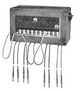 |
| N613 |
N610 |
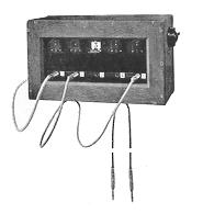
MAGNETO WALL PATTERN SWITCHBOARDS
A standard range of magneto wall pattern switchboards is also stocked, and an addition to these, the
N610 type, has recently been developed. This board is suitable for small installations up to a maximum of 20 lines, providing a simple and reliable system in cases where the number of calls is not excessive.
The following sizes are available:-
| Code |
Equipment |
| N610 |
20 lines and 5 through |
| N611 |
15 lines and 4 through |
| N612 |
10 lines and 3 through |
| N613 |
5 lines and 2 through |
All the above equipments are accommodated in a standard size teak modern design.
CIRCUITS
The line circuits are each equipped with a line jack and a 1000 ohm drop indicator which is permanently bridged across the line but is of sufficiently high impedance to prevent any appreciable loss of speech currents.
Connections between lines are made with 'straight through' cords, the clearing signal being given on the line indicators. Supervision is effected by means of an operator's plug and cord which connects to a standard magneto telephone mounted adjacent to the switchboard. An alarm buzzer fitted inside the switchboard may be thrown into circuit whilst the operator is temporarily off duty.
A distinct advantage of this type of switchboard is that whilst two parties are connected together it is impossible for the operator, either accidentally or intentionally, to overhear a conversation between them.
Only the most recent additions to the range of standard switchboards available from stock are included above. It is anticipated, however, that the more 'flexible' designs described will have a larger sphere of utility than the earlier types.
|
 ERICSSON
BULLETIN
No. 10
ERICSSON
BULLETIN
No. 10