|
THE NEW 'TYPE 1000' TELEPHONE
July 1957
The E.T.L. 1000 type telephone, available in table or wall patterns, incorporates an improved handset with rocking armature receiver and associated induction coil circuit to provide better transmission efficiency coupled with enhanced appearance. It enables improved performance to be obtained under existing line conditions or alternatively the present standards of transmission can be maintained using lines of greater length or lighter gauge.
THE 'export' table telephone, introduced in Bulletin No. 27 (January 1953), represents a step forward in design from the
N1002 shape which was our standard for many years. The 'export' case has proved very satisfactory and this shape is used with little modification for the 1000 type. The handset, however, is new, being more curved than previous models, with the microphone set at an angle which gives better acoustic performance. This permits the cup-shaped mouthpiece of the earlier type to be replaced by a more hygienic one. The curved handset matches the flowing lines of the case so that the two combine to form a telephone which is functionally efficient and pleasing in appearance.
A departure from previous practice has been made in providing two cup-shaped metal inserts in the telephone case, one on either side, which serve both as ventilation grilles and convenient lifting holds. The holes of the grille are screened with fine gauze.
In order to suit modern interior decoration schemes in homes and places of business, the new telephone is made in ten different colour assemblies. Seven of these are single-colour, and three dual-colour, the latter having the body in one shade and the handset and ventilation cups in another.
The dial fingerplate on black and ivory sets is stainless steel, while the others have a plastic fingerplate coloured to match the handset unless stainless steel is specified.
Careful study of the colour schemes has enabled the choice of colours for desk and handset cords to be restricted to four, so assisting stocking and maintenance.
Both table and wall versions of the Type 1000 telephone have been designed and are being produced in the same range of colours. A colour plate showing the complete range of table telephones is included in this Bulletin.
Following is a summary of the colours available:-
SINGLE-COLOUR TELEPHONES
| Telephone |
Cord(s) |
| Black |
Black |
| Ivory |
Maroon |
| Imperial red |
Maroon |
| Colonial blue |
Silver grey |
| Topaz yellow |
Green |
| Silver sage |
Silver grey |
| Forest green |
Green |
DUAL-COLOUR TELEPHONES
| Body |
Handset, etc. |
Cord(s) |
| Aircraft grey-green |
Forest green |
Green |
| French grey |
Elephant grey |
Silver grey |
| Blush Ivory |
Maroon |
Maroon |
The desk terminal block with each table telephone is coloured to match the body of the instrument and is of conventional
design - a moulded rectangular loose-lidded box containing screw terminals.
Like the table telephone, the wall set illustrated in Fig. 1 is characterized by its flowing contours. It has the same type of handset and a case of the form described in Bulletin No. 31 (January 1955).
 |
Fig. 1
Wall Telephone (Type N1096A) |
| |
 |
Fig. 2
Interior View of Table Telephone (Type N1025A) |
Table and wall telephones with either standard or tropical finish are available. Fig. 2 shows a table set of tropical type. The dial mechanism is protected by a dust cover of transparent plastic material, and external terminals are provided to enable the dial cord to be disconnected without removing the cover. The dial can be detached from the case after removing a single screw, and is protected against the ingress of dust from the front by a felt washer. Other features of tropical versions include shrouding and dust proofing of the cradle switch operating plungers, gauze covering of the ringer holes in the base to
prevent insects entering the case, varnish dipping of the cradle switch springs to prevent surface leakage, and varnish impregnation of the induction and ringer coils.
The case of the table telephone is easily detached, after slackening captive screws underneath, to reveal the components mounted on an aluminium alloy pressed sheet base. Rubber feet are inserted to avoid marking polished surfaces.
The backplate of the wall telephone is die cast - not pressed - aluminium alloy and is similarly fitted
with rubber feet. The case hooks on the top of the plate, to which it is secured by one screw at the bottom. When this is released, the case complete with automatic dial and cradle-switch plungers can be unhooked from the backplate and swung down on a webbing suspension which prevents the dial cord being strained.
The automatic dial is normally B.P.O. No. 12 trigger type with standard numbering and a
66.6 : 33.3 break-to-make ratio.
 |
Fig. 3
The Telephone Circuit |
The components are connected as shown in Fig. 3. The induction coil is of the closed magnetic path type specially designed for use with the rocking armature receiver and is more efficient than the open-ended wire-cored type previously used. Fig. 4 illustrates examples of old and new coils. In the table set the capacitors are held in rubber mountings one of which is a push fit in the base, the other being fixed on top of the dial cord terminal strip. The cradle switch is operated by a simple friction-free mechanism in which rollers attached to the plungers in the case move over a pivoted plate.
The blocks upon which the desk and handset cords terminate include a number of terminals wired to various points of the circuits so that modifications, such as for parallel working without bell tinkle, can readily be made. The internal wiring is in 25 s.w.g. with p.v.c. insulation, and the cord conductors also have p.v.c. insulation with nylon braiding over all.
The instruments can be arranged to accommodate auxiliary key circuits for various extension schemes, the maximum number of keys being three as on earlier types of telephones used for such schemes.
TRANSMITTER
The re-designed handset employs the B.P.O. No. 13 transmitter of the immersed-electrode
carbon granule type which has been in use for a number of years. In the new handset the transmitter is positioned nearer to the mouth, and under conditions of normal use is held at the angle of maximum sensitivity, that is, with the plane of the transmitter diaphragm at an angle of about 40' to the vertical. This results in an increase of from 2 to 3 db compared with the output obtained with the diaphragm vertical. It is sometimes found desirable to place a resistive shunt across the transmitter to reduce arcing between the granules. A resistor for connection to the appropriate terminals is available when required.
RECEIVER
The magnetic-diaphragm 2P type receiver previously employed is replaced by the rocking-armature
receiver which contributes most to the enhanced performance of the new telephone. In this receiver (Fig. 5) magnetic and acoustic functions are separated, the diaphragm being designed for optimum acoustic performance and driven by a small rod connected to the armature. The armature is fixed rigidly at each end of the frame and two thin torsion arms allow movement of the central portion. The two edges of the central portion are alternately attracted to their adjacent pole-pieces and hence impart a reciprocating motion to the diaphragm via the rod connected to the edge of the armature. The permanent magnet is a small rectangular block of anisotropic material. Its high reluctance is excluded from the alternating flux path by employing a balanced bridge type of magnetic circuit, so that the magnetic sensitivity is improved. The volume efficiency of the receiver is about 7 db better than that of the 2P receiver, and the frequency response curve is flatter as can be seen from Fig. 6.
 |
Fig. 4
Induction Coils, old (front) and new (rear) |
INDUCTION COIL
Since the new telephone will have to be used in conjunction with earlier sets for some time, maximum improvement will be obtained if sending and receiving performances are raised by about the same amount. For this reason the induction coil has been designed to utilize part of the receiver's increased efficiency in improving the sending performance of the circuit. The new induction coil shown in Fig. 4 employs laminations of grain-orientated silicon iron which gives low core-loss and increased permeability. This enables the required transformation efficiency to be obtained with fewer turns, thereby reducing copper losses.
CIRCUIT
Increased efficiency of the transmitter or receiver in a telephone set is accompanied by an equal increase in side-tone (the reproduction of the talker's voice in his own receiver) unless the side-tone balance network is improved. Fig. 7 shows the basic transmission circuit of the telephone. Transmitter speech currents i1 and i2 flow in the line and balance network circuits. A voltage i2Z therefore appears across the impedance Z of the balance network. At the same time an e.m.f. e is induced across winding 3, which, in series with the balance network, is connected
across the receiver. Hence if i2Z = e and the two voltages are in opposition there will be no current through the receiver and therefore no side-tone. When receiving, the signal from the line is divided between the receiver and the transmitter.
Absolute balance is not obtainable in practice since this would require perfect matching between the line and the balance network at all frequencies. Moreover, it is not desirable since it would make the telephone sound 'dead' when spoken into. A suitable circuit can, however, give good side-tone suppression over the range of line conditions encountered in a normal telephone system. The balance network shown in the circuit diagrams (Figs. 3 and 7) consists of two resistors and two capacitors and enables the side-tone suppression of the new telephone to be maintained at the same general level as in telephones of lower efficiency. In order to make convenient use of the balance network components in the dial spark quench circuit, the common terminal
for transmitter and receiver has been omitted ; hence a 4-way handset cord is used.
This also enables the handset connections to be made directly to the transmitter and receiver
(3) terminals, no internal connecting lead being necessary.
| (1) Frame with magnet and coil assembly
(2) Diaphragm added
(3) Terminals added and coil wires attached
(4) Complete
|
 |
|
Fig. 5A
Stages of Receiver Construction |
 |
Fig. 5B
Enlarged view of Rocking Armature as seen from reverse side of Fig. 5A(1) |
LINE CURRENT
The current drawn by a telephone from the exchange battery depends largely on the
distance between the telephone and exchange and on the gauge of wire connecting them, decreasing as the resistance of the
(1) circuit increases.
The resistance
of the carbon-granule transmitter increases with decrease of current, and therefore further
reduces line current on long lines. This effect is small, however; a change of line resistance from 0 to 1000 ohms
results in a change of only about 30 ohms in transmitter resistance.
The maximum current is about 100 milliamps. It is obtained when the telephone is connected by a very short length of line to an exchange employing a 50-volt battery and 200 +200-ohm feeding bridge, the combined resistance then being just under 500 ohms. The minimum current in conditions of satisfactory operation is just under 30 milliamps, through a line loop resistance of 1300 ohms. Fig. 8 shows the variation of line current and telephone resistance for varying loop resistance.
PERFORMANCE
The efficiency of a telephone can be measured in several ways, some objective, some subjective. For production testing objective methods are used. In this case the sending, receiving and side-tone performance of the set is measured over a band of frequencies in comparison with a standard instrument of the same type. In assessing the relative merits of different types of instrument, however, subjective methods are desirable since these can take into account the fact that in determining the performance of a telephone the main criterion is the degree of satisfaction experienced by the user. Subjective measurements may involve comparisons of volume between two instruments, articulation or intelligibility of messages or groups of phrases, or expression of opinions after a normal conversation over a telephone circuit. In some cases a trained speech-testing team is employed, in others it is found preferable to use untrained people. Mathematical treatment of the
results is generally necessary to obtain figures expressing transmission performance; hence such methods are neither suitable nor necessary for testing on production lines where the tests are carried out on a 'pass-reject' basis.
 |
Fig. 6
Receiver Response |
| |
 |
Fig. 7
Transmission Schematic |
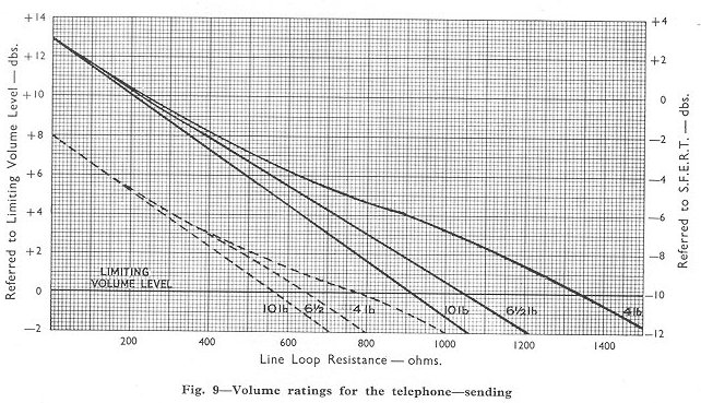
The performance curves of the new telephone and the B.P.O. standard telephone No. 332 (dotted lines) determined by two methods are shown in Figs.
9-12. Figs. 9 and 10 show the sending and receiving performances assessed on the basis of volume. The scale on the left gives the rating relative to a minimum standard defined by the British Post Office. This minimum is the performance obtained from a Telephone No. 162 (the predecessor of the 332 type) connected by a 450 ohm loop of 10 lb. per mile cable to a 50-volt exchange with a 200 +200-ohm feeding circuit. The scale on the right gives the rating with reference to the datum fixed by S.F.E.R.T. (Systeme Fondamental Europ'en de R'f'rence pour la transmission Telephonique).
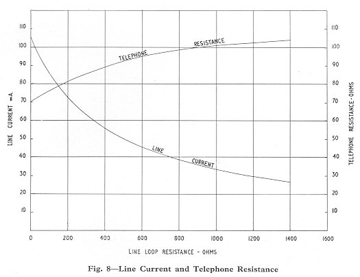 |
| Fig. 8'Line Current and Telephone Resistance |
This master telephone transmission reference system, maintained by the International Telegraph and Telephone Consultative Committee (C.C.I.T.T.) at Geneva, consists of a high quality microphone and receiver which can be coupled via amplifiers, attenuators and distorting networks to enable comparison to be made between the reference system and telephone circuits. The reference levels are arbitrary. The C.C.I.T.T. recommendations for the minimum levels for national local circuits are as follows:-
Sending: -18 db with reference
Receiving: -13 db) to SFERT datum.
These are somewhat lower than the minimum levels maintained on local lines in the United Kingdom.
It will be seen from the graphs that the rating for the new telephone compared with the 332 type is 5 db higher for sending and 3 db higher for receiving.
The different performance which each telephone exhibits using cables of various gauges is explained by the fact that the capacitance per unit length of the three types of cable is the same, hence the capacitance and
attenuation per unit resistance is greater for the heavier gauge cables.
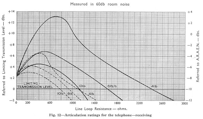
Articulation ratings are shown in Figs. 11 and 12. In this case the performance is determined by the
percentage of meaningless syllables which are received correctly. The A.R.A.E.N. (Appareil de
Ref'rence pour la determination des Affailblissements Equivalents pour la Nettet') takes into account the effect of the side-tone and room noise on reception. The acoustic intensity of the room noise employed for the tests is 60 db above a reference point fixed at 2 x
l0 -4 dyne/cm2 at 1000 cycles/second. The figures show that although the performance on short lines is about equal, the new instrument has considerably improved performance on longer lines and reduces the limitations imposed by line length and gauge.
Articulation rating for reception can be seen to increase initially with increasing line length. This is due to the side-tone effect. Fig. 13 shows the relative electrical side-tone suppression achieved by the two telephone circuits, from which it can be seen that the side-tone suppression of the new instrument is more effective on longer lines than on very short lines. The graphs are derived from the side-tone levels at 500, 1000, 2000 and 3000 cycles per second.
The improved appearance of the 1000 type telephone is thus accompanied by enhanced performance, so that the new instrument shows advantages over its predecessor in all respects.
 |
 |
 |
 |
 |
Fig. 13
Electrical Side-Tone Suppression |
The rocking armature receiver has now been standardised by the B.P.O. and was
developed by Messrs. Standard Telephones & Cables Ltd in conjunction with
the B.P.O. engineers.
|
 ERICSSON
BULLETIN
No. 35
ERICSSON
BULLETIN
No. 35