ERICSSON
BULLETIN
No. 52 ERICSSON
BULLETIN
No. 52PAGE No. 28 | ||||||||
|
Pressetel This press button telephone will work to any loop/disconnect system capable of operation by the conventional dial, and can also be adapted to systems permitting much higher digit signalling rates than are mechanically possible using the dial. No exchange modification is
necessary - Pressetel is the simpler of two possible design approaches fulfilling this requirement, and is thus most economic for general subscriber
use. Press button signalling is being introduced into telephone systems to enable the subscriber to save time in the setting up of calls. In practice this saving is more than that conferred by increased signalling speed alone; with the ability to deal with the digit sequence more quickly there is less strain on the short-term memory performance of the subscriber. Wrong numbers due to subscriber error - a major source of lost time when they occur - are therefore less likely. A parallel improvement is the lessened preoccupation with the mechanics of signalling, as compared with use of a dial. Simple layout of the press buttons, larger digit areas and the absence of distracting movement are factors contributing to this. In the provision of press button facilities there are two main approaches. The first is in the type of instrument which permits the user to operate the press buttons at speeds as fast as his physical capabilities allow. A multiple store is necessary to enable the digital information to be re-transmitted to line at the rate required by the exchange equipment. Such a store with its associated sequencing elements is necessarily complex and, at the present state of manufacturing technique and component costs, an instrument of this type will be too expensive for some subscribers. The second approach is represented by a simple and more economic type of instrument, using a single digit store. Successive digits can be keyed into this store
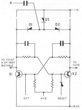
at a rate governed by the requirements of the exchange. The information corresponding to each digit is converted into line pulses and, when these have been transmitted, the next digit may be keyed in. The function is analogous to that of the conventional dial, but electronic techniques permit a keying rate to be achieved which is the actual maximum the exchange will accept; certain features of dial operation preclude this possibility. A principal operating feature of Pressetel is that keying of a digit into the store can take place during the interdigital pause period. To permit the user to take full advantage of this facility and so achieve maximum signalling rate, a 'signal barred' lamp is extinguished at the end of pulsing. When a digit is stored, a gate controlled by the store is closed and a switching circuit associated with the gate removes an inhibit condition from the pulsing device, an astable multivibrator. This free-runs, pulsing an 'A' relay to transmit pulse signals to line. The multivibrator also feeds pulses at the same rate back to the store which counts down to the 'home' condition. This is reached when the number of pulses transmitted is numerically equal to the digit stored. The gate controlled by the store now opens and re-imposes the inhibit condition on the multivibrator. During pulsing, off-normal relays are operated by the switching circuit associated with the gate. One of these (ONA) causes the 'Signal Barred' lamp to glow. At the end of each pulse train a timing device, the Inter Digital Pause (IDP) Generator, is operated to place a second inhibit condition on the multivibrator, independent of that from the store-controlled gate. Therefore, although the next digit may be stored at any time after the end of pulsing, the multivibrator will not free run until the IDP inhibit is removed. A fixed minimum delay is thus obtained between the pulse trains. Considering the bistable in figure 1 as the first in the chain, the waveform from the multivibrator is fed in at point A. This waveform is differentiated to produce positive and negative pulses which are applied to the junction of diodes Dl, D2 and D3. Only the positive pulses are effective because of diode blocking action. There is one such effective pulse, termed an input pulse, per line pulse. Each input pulse is steered by Dl or D2 to the collector of whichever transistor happens to be 'off', causing this transistor to be turned 'on' and the bistable to change state from '0' to '1' or from '1' to '0'.
It will be seen that transistor Xl goes from an 'off' to an 'on' condition with alternate changes of state. The resultant positive-going potential step at Xl collector is fed to point A of bistable No. 2. This bistable thus changes state upon every second input pulse to the store. Similarly bistable No. 3 changes state upon every fourth pulse and bistable No. 4 changes state upon every eighth pulse. If the store were initially reset to the '0000' (home) condition, it would reach a '1111' state on the 15th pulse and revert to the '0000' state on the 16th. Each intermediate state is unique, i.e. involving a different combination of 'l's and '0's from any other. The most convenient way to store a digit 'x' is to set the store to the state it would have reached if
(16-x) pulses had been fed in. Then 'x' actual pulses will return it to the '0000' or 'home' condition. This method of storage is adopted in Pressetel. To control the multivibrator the gate associated with the store need only distinguish between the '0000' state and any other; a relatively simple requirement.
When the store is in the home condition all of these transistors are 'off' and a negative output is provided from the gate to the transistor switch. This switch is as a result 'on', which causes the control transistor to be switched 'off' and the multivibrator to be prevented from free running; the 'A' relay is held operated. When a digit is stored, i.e. one or more bistables are in the '1' state, the diodes associated with these
bistables conduct more heavily and the gate output potential is now such as to turn the transistor switch 'off', provided that no inhibit is being applied by the IDP generator. The control transistor is accordingly switched 'on', and the multivibrator free-runs. This event is used to initiate the IDP. A pulse developed by the bistable triggers the IDP generator, which is a monostable multivibrator, to the quasistable state. This state, of duration equal to the required IDP, is marked by a reversal of conditions in the monostable; the normally 'off'transistor is 'on' and the normally 'on' transistor 'off'. The resulting output potential from the collector of the latter is applied to the transistor switch (figure 2). Its effect is to override the control exercised on this switch by the gate. Thus, irrespective of whether a new digit has been stored or not, the multivibrator cannot free-run until the IDP has expired.
The majority of the logic-circuit components are assembled on two printed cards seen parallel to the base of the instrument and towards the front. The lower card is secured by screws to the baseplate and the upper card, which carries the two preset controls for make/break time adjustment, similarly affixed to brackets projecting downwards from the
press button assembly. The latter can be readily detached by withdrawing screws securing it to the baseplate and instrument bracket, and the whole assembly swings aside to allow either the upper or lower card to be inspected or, if necessary, removed. A 12V supply would normally be obtained from a small a.c. mains-operated rectifier unit mounted at some convenient point near the instrument. Supplies of 24V, or more usually 50V, could, for instance, be obtained over an additional pair of wires from the exchange. The transistors and electrolytic capacitors are fully protected against damage from the accidental reversal of supply polarity.
|
||||||||
Last revised: October 15, 2019FM3 |