|
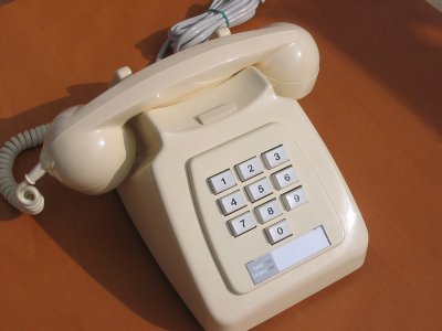
 The second generation battery keyphone, Telephone No. 764 Mark 2 (the Keyphone), was introduced in 1976. The Keyphone was now generally available to subscribers following market trials in 1972 and even earlier trials as far back as 1963. The most striking and original feature of this new telephone was the keypad instead of the conventional dial. With the rapid expansion of subscriber dialling of trunk and international calls, longer telephone numbers had to be used. Keying these numbers was an easier operation than dialling in the traditional manner. Microelectronic circuitry beneath the keypad stored the numbers and transmitted them to the exchange at the normal speed. The second generation battery keyphone, Telephone No. 764 Mark 2 (the Keyphone), was introduced in 1976. The Keyphone was now generally available to subscribers following market trials in 1972 and even earlier trials as far back as 1963. The most striking and original feature of this new telephone was the keypad instead of the conventional dial. With the rapid expansion of subscriber dialling of trunk and international calls, longer telephone numbers had to be used. Keying these numbers was an easier operation than dialling in the traditional manner. Microelectronic circuitry beneath the keypad stored the numbers and transmitted them to the exchange at the normal speed.
Previously called the "Keyphone - Self Contained (SC)" this phone
was later renamed "Push Button Telephone - Self Contained (SC)".
Telephone No. 1/8764 and 2/8764
In 1982 the Telephone No. 1/8764 and 2/8764 (Ivory and Grey) were introduced
and they were fitted with a Bell No. 59D-1 (high
impedance bell coils 4000 ohms) and a Cord Connection No. 4/502 3000mm. Both these phones were recycled Telephone No.1/764 and 2/764's.
Superseded by the Telephone No. 756.
Circuit diagram - N864
(Telephone No. 764) and N8864 (Telephone No.
8764).
Specification - S975.
Replacing
batteries in a Battery Secondary No. 23
TELECOMMUNICATIONS INSTRUCTION
C MARKETING INSTALLATION
3 Internal
B3022
Issue 2, April 75 SELF-CONTAINED KEYPHONE TELEPHONES
No. 1/764 AND 2/764 GENERAL
 This instruction describes and gives information on 10 pulses per second self-contained keyphones based on Telephone 746. This instruction describes and gives information on 10 pulses per second self-contained keyphones based on Telephone 746.
DESCRIPTION
Telephone No. 1/764 and 2/764 differ from Telephone
No. 746 in that a push-button unit (pbu) and escutcheon plate replace the dial and outer number ring. A recess is provided below the keypad to take the subscriber's number label.
The (pbu) occupies the same mounting as the dial it replaces. The instruments accepts the standard range of add-on parts.
The electronic circuits are powered by rechargeable nickel-cadmium batteries. Battery secondary No. 22 is used for
Telephone No. 1/764 and Battery secondary No. 23 for Telephone No. 2/764. Plugs and sockets are provided to connect the battery to the telephone. To facilitate correct identification Battery secondary No. 22 is housed in a red plastic case and Battery No. 23 in a blue plastic case.
The base of the Telephone No. 1/764 bears the legend:- USE BATTERY SECONDARY
No. 22
- (coloured red) - pictured to the right.
The base of Telephone No. 2/764 bears the legend:- USE BATTERY SECONDARY
No. 23
- (coloured blue)
 BATTERY CHARGING BATTERY CHARGING
The batteries may be charged from the line while the telephone is "on-hook", or from a Power Unit No. 53 where line charging is not possible - see Diagram N 864 for details. When the battery is line charged, a charge switching unit (CSU) is incorporated to disconnect the charging circuit during periods of line testing.
FIELD OF USE
With the addition of auxiliary apparatus as required Telephone
No. 1/764 and Telephone No. 2/764 are suitable for use on Exchange lines (exclusive and shared), PBX extensions (with or without recall) and those extension plan installations which could otherwise be met by the provision of Telephone
No. 746, except for the following:- -
Extension Plan 4 with more than one keyphone. -
In conjunction with Lamps Signalling Nos. 1 and 2. If a Telephone
No. 1/764 or 2/764 is required on an extension plan where pre 700 type telephones exist, other than on the extension plans 5, 5A, 7 and 7A using Bellset 20, 39 or 44, all earlier types of instrument must be replaced by 700 type.
DETAILS OF CHARGING ARRANGEMENTS
Charging over Exchange lines or 50v PABX extension lines may be employed for one Telephone on Exclusive DEL and Extension Plans on the following:-
Shared Service Lines and Extension Plans Charging facilities are dependent upon the calling equipment used in the exchange. -
Uniselector per line, 200 pt line finder, UAX and TXK- calling equipment's allow line charging for one Telephone
No. 1/746 and 2/746 on each party. -
50 Pt line finder, TXE2 calling equipment's restrict line charging to one Telephone
No. 1/746 or 2/746 to one party only.
Subject to the above, the following application may be met:-
50v PABX direct extensions and associated extension plans excluding PABX1 extensions arranged for direct extension night service, line charging may be employed for not more than one Telephone
No. 1/746 or 2/746 (per extension line) on the following:-
Charging from Existing 50v or 12v Local Power Supply
This method should be adopted for:- -
Main of Plans 105, 107, 105A and 107A; two additional connections are required to extend the 12v supply from the
Plan-set N625 to the charging circuit of the telephone. -
Charging from the switchboard 50v SUPPLY should be employed for the operating telephone of 2/..... switchboards, and from the 50v SUPPLY for the operating telephone associated with Key and Lamp Units.
Charging from Power Unit Provided for this Purpose (except for those with power supplied already), all other applications will require the provision of a power unit. In addition, a power unit must be provided in lieu of the line charging, when switching facilities are provided to divert the line from the telephone to other equipment. Power Unit 53A should be used and, if required, up to 80 keyphone batteries may be charged from one power unit. An instrument cord with extra conductors and a larger block terminal than that shown in the appropriate N diagrams may be required.
AUXILIARY UNITS
Telephone No. 1/764 and 2/764 will accept the same auxiliary units as
Telephone No. 746 (see Diagram N848) except Strip Connection
No. 155A and Lamps Signalling Nos. 1 and 2. When Clip No. 90 is required it should be fitted in the normal position.
OPERATION
To make a call, lift the handset and, on receipt of dial tone, key in the number, one digit at a time. It is not necessary to pause between key operations while a digit is pulsed out, unless an access digit is keyed in which case dial tone must be obtained before proceeding.
INSTALLATION
For information see Diagram N 864.
When Power Unit No. 53A is required it should be installed in accordance with C3 Q0020.
Ensure that the handset is replaced on the rest to prevent excessive battery drain. For the same reason. Plan 4 portable keyphones should always be left plugged into the line socket.
The pulsing of Telephone No. 1/764 and 2/764 is identical to that of a normal dial telephone and can be tested for speed and ratio in the normal manner. Tests should be carried out when commissioning keyphones to ensure the correct pulsing out of all digit buttons.
CARRIER CIRCUITS
When Keyphones are required on either the physical or carrier circuits of 1 + 1 Carrier it will be necessary to provide a Power Unit.
Advice Notes should be checked by Distribution Officers before issue to installation staff in order that arrangements can be made for a power point to be available.
POWER CIRCUIT STRAPS
To change between the different methods of battery charging, straps within the telephone must be moved. The telephone is supplied with the Battery strapping set to Line
charging and the charging leads connected to T9 (yellow) and T19 (green).
Line
charging - Terminals T26 - T27 are strapped together.
For 50v local power feed - connect power (see next paragraph) to the telephone, remove strap from T26 - T27 and strap across T27 - T28.
For 10v local power feed -
connect power (see next paragraph) to the telephone, remove strap from T26 - T27 and strap across T28 - T29.
When
using a local power (external) feed, move the yellow & green wires from T9
& T19 and terminate them on spare terminals (T11 - T15 are usually
spare). Then connect the local power source to these terminals.
CHARGING CHECK
Line charging
To check the charging circuit connect a milliameter in place of the strap T26 (-ve) and T27 (+ve). With the handset on the rest a current of 2 - 3mA should flow after 30-100 seconds. Replace strap after testing.
Charging by local PSU
To check the charging current connect a milliameter in place of the strap T27 (+ve) and T28 (-ve) for 10v PSU's or T29 (+ve) and T28 (-ve) for 50 v PSU's. With the handset on the rest the current flow should be 2 - 3mA. Replace strap after testing.
Additional information
| Model |
Mark |
Ivory | Grey |
PBU No. |
Introduced |
Remarks |
| Tele No. 1/764 |
Mk 1 | y | y |
| 4/73 |
Uses Battery No. 22
(red) | | Tele No. 1/764Z |
Mk 1 | y | y |
| 11/76 |
Uses Kit No. 237A | | Tele
No. 2/764 | Mk 1 |
y | y |
| 4/73 |
PYE/TMC uses Battery No. 23
(blue) | | Tele No. 2/764 |
Mk 2 | y | y |
| 5/76 |
PYE-TMC cost reduced version |
| Tele No.
1/8764 | Mk 1 | y | y |
| 3/82 |
| | Tele No.
2/8764 | Mk 2 | y | y |
| 3/82 |
|
|