| Sales Brochure -
DLE520.
User Guide
Maintenance
Guide Notes
POEEJ Article -
1960
TELECOMMUNICATIONS INSTRUCTION
C MARKETING INSTALLATION
3 Internal
M1001
Issue 2, Aug 73
ANSWERING SET No. 1A
Description and Installation
INTRODUCTION
 This
Instruction describes the various types of Answering Set No. 1A, which supersede the now
obsolescent Answering Set No. 1 (made by Sontronic Ltd). The Old No. 1
used valves and 3000 type relays in it's circuitry. Tape movement was
controlled by a microswitch associated with the pinch wheel. When the join
in the tape passes the pinch wheel the microswitch operated. The join in
the tape is thicker (0.02) than a normal join. This
Instruction describes the various types of Answering Set No. 1A, which supersede the now
obsolescent Answering Set No. 1 (made by Sontronic Ltd). The Old No. 1
used valves and 3000 type relays in it's circuitry. Tape movement was
controlled by a microswitch associated with the pinch wheel. When the join
in the tape passes the pinch wheel the microswitch operated. The join in
the tape is thicker (0.02) than a normal join.
GENERAL
The facilities, connection and operating procedures of the different versions are the same
and this instruction will detail the differences in design and construction. The circuits
are shown on Diagram SA5202, and Diagram Notes SA5202 explain the circuit operation of
the machines.
FACILITIES
The Answering Set No. 1A is a device for use in a subscribers premises for the purpose of
answering telephone calls automatically and playing a recorded message to callers. The
message is of 20 seconds duration and is played twice to the caller. Recordings, on a loop
of magnetic tape, are made and checked by means of the associated telephone. Transmitter
current is supplied to the telephone from the answering set when it is switched to the
Check and Record positions. The answering set operates from a mains supply of
200-250v ac
50 Hz. It is suitable for use in auto and CB exchange areas on exclusive DEL's, PBX
extension, extension plans and HES. The answering set is not suitable for use on shared
service lines or in magnet areas.
The answering set is not designed for direct connection to a switchboard e.g. in place of
the operators' telephone. It may, exceptionally, be used with a PABX extension arranged
for direct night service (see TI C3 F1010 and C3 F1014).
INSTALLATION
The answering set must, generally, be associated with a telephone and cannot as supplied,
be used by itself. The telephone should be fitted adjacent to the answering set so the
time indicator is visible whilst a recording is being made. Diagram N 4190 shows how the
telephone and answering set are connected to the line.
When the answering set is to be associated with an extension plan installation or an HES,
an additional telephone must be fitted for the purpose of operating the set.
(a) Mains power Supply
The answering set requires a 200-250V 50 Hz mains supply. A 3 pin socket outlet should be
provided by the subscriber within 10ft of the position of the set. The PO will provide
the appropriate mains plug.
(b) Connecting the answering set
-
Remove the case and base (see Constructional Features for appropriate
machines). The voltage adjustment panel is reached by removing the Danger label; the
connections on this panel are soldered.
-
Fit the appropriate mains plug.
-
Connection to DEL or PBX extension Terminate the 6 way answering set cord on a Block
Terminal No. 35A. Change the telephone line cord to a Cord Instrument No. 6/61 AT.....
3000 mm and connect as shown in N4190.
-
Connection to extension plan or HES Change the answering set cord to a Cord
Instrument No. 9/21 AD GREY 3000 mm and connect as shown in N4190.
PRECAUTIONS DURING INSTALLATION
The mains plug must be
withdrawn before any work is done on the machine. Permanent magnets or magnetised tools
must not be brought near the record/replay head of the machine. The output of the set will
be affected if the head becomes magnetised.
Care should be taken to ensure that the machine is not installed in the proximity of
strong a.c. fields and that the leads to the answering set are not routed near machinery
likely to generate interference fields.
After installation all the spindles and wheels in the tape drive system where friction
drive is used should be wiped with a clean dry cloth to remove dust and grease which could
cause slipping.
Before the cover is finally replaced ensure that the pointer moves freely over the whole
length of the time indicator scale.
OPERATING THE SET
A copy of the operating instructions should be handed to the subscriber at the time of
installation but it is desirable that the fitter should ensure that the subscriber is
familiar with the facilities provided and the method of using the set.

The Answer Set No. 1A/2 uses a lamp instead of the
indicator to show the motor is running
The following notes summarise the operating instructions:-
(a) Recording
Switch the control knob to Record. Lift the handset, press the Start button firmly and
then release it. As soon as the indicator pointer appears, speak normally into the
mouthpiece and continue until the pointer disappears. It is desirable to avoid gaps during
or at the end of the message.
(b) Checking
When the motor indicator stops turning switch to Check, press the Start button, and listen
to the message on the handset. The message will only be played once.
(An incoming ring during either of the above operations will ring the telephone bell and
the call can be answered by turning the switch to Off and using the telephone normally.)
(c) Answering
Switch to On and ensure the mains supply is connected. An incoming call will ring the
telephone bell for 5-10 seconds before the set answers automatically. During this period
the call can be intercepted by the telephone by turning the switch to Off and using the
telephone in the normal way. If a call has been intercepted in this manner the set must be
restored to its starting condition by switching it to Check and pressing the Start button.
If it is required to use the telephone normally switch the control knob to Off.
When the answering set is associated with an extension plan or HES the operation differs
as follows:-
The telephone associated with the answering set may be used for intercepting calls to the
answering set only when the switch is in the On position. In all other switch positions
the exchange line is not connected to the associated telephone but to the extension plan
or HES. When the switch is in the On position the extension plan is disconnected.
ANSWERING SET No. 1A/1
The Answering Set No. 1A/1 is manufactured by Sontronic Ltd and with the exception of the
connections differs completely from other versions of the answering set. The machine is
fully transistorised and the ringing delay and tape control are achieved by electronic
circuitry and photo-conductor and lamp.

Details of the constructional features peculiar to this machine are given in the following
paragraphs.
(a) Removal of case
(i) Remove knob of 4-position switch using Wrench, Hexagonal, No. 1 to
release the socket-head grub screw. A wrench can be found set into the base and held by
one of the 4 large screws.
(ii) Remove the screws at each corner of the Perspex panel. This panel and the main case
may now be removed.
(iii) remove the base which is secured by 4 large screws; the 15-way terminal strip for
connecting the set is then exposed.
(b) Chassis assembly
Removal of the front plate and case will reveal the top face of the chassis. Mounted on
the top face of the chassis are the tape tray, tape drive system, mains-on lamp, control
switch, start button, line transformer and recording time indicator. On the underside of
the chassis are mounted the mains connection blocks and fuse, mains transformer, tape
drive motor, and the wafer assembly of the control switch. The chassis is mounted on 2 end
brackets to which the moulded base is secured.
(c) The printed wiring board
This is secured to the vertical members of the 2 end brackets by 4 fixing nuts. The
printed wiring side of the board is insulated by a sheet of impregnated paper covering the
whole of the rear face. All circuit components are mounted on the inside face of the
board, including relay A which is a PO type 25 relay mounted on a stand-off bracket and
wired into the printed circuit. The ringing detector, consisting of lamp and
photo-conductor, is mounted under a cylindrical cover retained by a helical spring. To
obtain access to the ringing detector it is necessary to release the retaining spring and
withdraw the cover. Adjustment of the ringing delay period is provided by potentiometer
VR1 located close to the ringing detector. The terminal. strip for cord termination and
strapping is mounted on the printed wiring board.
(d) Tape drive and control
All moving parts associated with the tape driving mechanism and the multiple-wager
4-position control switch, are fitted to the sloping member of the chassis, either on top
or beneath it. Tape control is achieved by a photo-conductor lamp and a small hole in the
tape. The photo conductor is mounted in a masking assembly on the tape tray wall through
which a hole is drilled to allow light from the lamp to impinge on it. The lamp is mounted
in a plastic holder and protrudes through the base of the tape tray opposite the
photoconductor. The plastic holder slides on a lug secured to the underside of the tape
tray so that the lamp position can be adjusted with respect to the tape hole and
photo-conductor. A grub screw is provided in the plastic lamp holder to ensure that lamp
position adjustment is maintained. The spindle of the tape-drive motor extends through the
chassis. The motor is supplied with 48V a.c. from the mains transformer whatever the
supply voltage. The spring loaded idler-wheel transmits the drive to the rim of the
flywheel. The extended spindle of the flywheel imparts driving force to the tape which is
pressed against it by the rubber pinch-wheel. The pinch-wheel is mounted at one end of the
pivoted lever; pressure between the pinch-wheel and the driving spindle is maintained by a
spring which exerts a pull of 3lb. on the lever. The top of the rubber pinch-wheel has a
moulded pattern which is visible through the window in the case.
When the flywheel is being driven by the motor, the tape is given a linear velocity of
approximately 1.9 in/sec. The tape is pulled out of the storage tray at the upper
left-hand corner and passes the erasing head and the record/replay head before reaching
the pinch assembly. After passing through the pinch assembly the tape is wiped by an
earthed strip to remove electrostatic charges which might cause the convolutions of tape
to stick to each other in the storage tray. Under the influence of its forward movement,
the tape packs itself into the tray; the lid of the tray, which also carries the scale of
the time indicator, must not be removed while the tape is in motion or the tape will spill
out and may break or kink.
While the tape is in motion, pressure pads keep it in intimate contact with the erase and
record/replay heads, but when the control switch is in the Off position a cam on the
switch shaft causes the lever to lift the pinch-wheel and the pressure pads away from the
tape.
The flywheel is fitted with a concentric plastic disk in which is cut a spiral groove from
the centre to the edge. A nylon stylus tracks across the disk during the recording and
checking of a message. The stylus is attached to a cranked and pivoted arm having, at its
free end, a pointer which traverses the scale in the centre of the control panel.
Operation of the Start button lifts the stylus from the rim of the disk and allows it to
fall under gravity to the start of the spiral; at the same time the pointer moves to the
Begin Recording position on the scale.
(e) The recording tape
The tape loop is made up from standard 0.25 in wide recording tape 38.5 in long with the
ends joined.
A small hole is punched in the tape, off-centre, near the joint, so that it passes
between the photo-conductor and lamp.
The tape should not be handled otherwise the performance of the set will be impaired, but
if for any reason it becomes necessary to replace the tape in the storage tray the
following procedure is recommended.
Turn control switch to Off.
Remove lid of tape tray.
Remove the existing tape.
Feed the tape past the erase and record/replay heads and through the pinch assembly. The
matt side of the tape should be against the heads and the small hole is near the
lower edge. Feed the tape past the heads and through the pinch wheel
until the hole has
emerged from the pinch-wheel assembly.
Pass both parts of the tape through the slot in the lower right-hand corner of the tape
box. The tape must be free of twists and kinks and it is better to have it hanging free,
e.g. over the edge of a table. The tape may be pulled very gently to straighten it.
Replace lid of tape tray.
Turn switch to Check and press Start button. After the tape has been drawn into the tray,
the tape drive will be disconnected. A new recording must be made after replacing the tape
even if the tape has not been renewed.
(f) Spring adjustments
Screw adjustment is provided for the tensioning springs of the pinch wheel, idler wheel
and pressure pads.
ANSWERING SET No. 1A/2
The Answering Set No. 1A/2 is manufactured by Ansafone Ltd and with the exception of the
connection differs completely from other versions of the answering set. The machine is
fully transistorised and the ringing delay and tape control are achieved by electronic
circuitry and photo-cell and lamp. Details of the constructional features peculiar to this
machine are given in the following paragraphs.

(a) Chassis Assembly
The case can be removed by the same procedure as for the Answering Set No. 1A/1 except a
screw driver is used to loosen the switch knob instead of an Allen key. Removal of the
front plate and case will reveal the top face of the chassis. The tape runs round a series
of pulleys, one of which is fixed in a slot to provide an adjustment. The tape is
tensioned by a spring on the right-hand side of the chassis. The tape drive system,
machine on lamp, machine-in-use lamp, start button, the set-level control and the
recording time indicator are mounted on the top of the chassis. To gain access below the
chassis 4 screws in the corners of the chassis should be removed. The chassis may then be
hooked under the front corners of side brackets which will retain the chassis
horizontally. The 2 end brackets are mounted on the base, the left-hand bracket has the
control switch and relays fitted to it, and the right-hand bracket has, the mains
transformer and fuse mounting fitted to it.
(b) Printed wiring board
The printed wiring board is retained at the base between 2 rubber bushes and the side
brackets, and at the top by the lip on the chassis. A plastic sleeve is fitted on the top
edge of the board to prevent damage when the chassis is replaced.
(c) Tape drive and control
The tape-drive motor, which is driven from a 40V tapping of the mains transformer, is
connected to the flywheel by a rubber drive belt. The extended spindle of the flywheel
forms the capstan spindle which imparts the driving force to the tape when it is pressed
against it by the pinch wheel. The spindle of the pinch wheel drives the indicator wheel
which in turn drives the tape indicator. Tape control is achieved by a photo-conductor, lamp
and a small window in the tape. The photo-conductor is mounted in a masking assembly
under the tape lid cover which has a hole drilled in it to allow light from the lamp to
impinge on it. The lamp is mounted in a metal holder which is fitted in a rubber grommet
in the chassis.
(d) Spring adjustments
The pressure adjustment of the pinch wheel can be adjusted by loosening the screw at the
back of the pinch solenoid and sliding the pinch solenoid backwards or forwards as
required. Care should be taken to ensure that the solenoid and the spring attaching it to
the pinch wheel bracket are in a direct line.
(e) Recording tape
This is identical to that used on the Answering Set No. 1A/1 except a small window is
provided near the joint so that it passes between the photo conductor and the lamp.
When replacing the tape, all that is required is for the tape to be put in place
and tensioned. The adjustable pulley wheel will account for any
differences in tape length. The pulley is held by a screw which is
accessible after removing the front deck plate of the machine.
Introduced in 1958
An extract from
THE POST OFFICE ELECTRICAL ENGINEERS' JOURNAL
Volume 53, Part 1, April 1960
An Answering Set for Telephone
Subscribers
Answering set No. 1
Design requirements are suggested for a device which will
answer a telephone call and give a recorded message when the called
subscriber is absent. The way in which these requirements are met by the
Post Office Answering Set No. 1 is described.
INTRODUCTION
For many years it has been possible for subscribers connected to certain
exchanges to arrange for incoming calls to be intercepted at a manual board
and for callers to be referred to an alternative number. This service is
particularly valuable to subscribers such as doctors, who can expect to
receive urgent telephone calls at any time and who are thus relieved of the
necessity of ensuring that someone is always available to answer them.
Unfortunately, this transfer-of-calls service cannot be made available to
all subscribers who might wish to use it, and there is a need for an
automatic answering device which can be associated with the telephone
installation whenever it is not convenient for calls to be answered
personally.
GENERAL DESIGN CONSIDERATIONS
It was considered that an answering machine for subscribers� use should
provide the following facilities:-
-
The user should be able to record the message he
wishes the caller to hear, and change it as required.
-
The subscriber.s telephone should be used to record
the messages, and the recording process should be no more difficult than
making a telephone call.
-
The user should be able to check the recording he has
made by listening to it in the telephone receiver.
-
The message capacity of the machine must be adequate,
but not greater than can conveniently be used fully. To help in this
respect, there should be an indicator showing the time available
throughout the recording process.
-
A caller should be able to hear the whole message at
least once, even if part of its transmission is interrupted
by pay tone from a pay-on-answer coin box.
-
Connexion of the machine must not interfere with
normal use of the subscriber's installation, and all incoming calls
should ring a telephone bell.
The machine described in this article is not required to
record the caller's message; other approved machines are already available
which will do this.
ANSWERING SET No. 1
Physical Features
An answering device, developed commercially to meet a Post Office
performance specification, has been adopted and coded as "Answering Set No.
1". It is an a.c. mains-operated machine using standard tape-recording
techniques and used with a Telephone No. 706.
The moulded case of the answering set, which follows the general
configuration of the Telephone No. 706, is approximately 12in. wide, 6in.
high and 9in. deep; it is two-tone grey in colour.
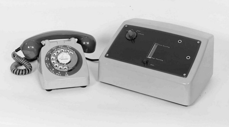
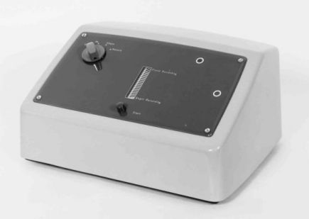
ANSWERING SET No. 1 WITH TELEPHONE No. 706
Only two controls are needed to operate the set; these
are a function-selector switch having the four positions �Off�, �On�,
�Check� and �Record�, and a press button which starts the machine when a
recording is to be made or checked. Three indicators are provided. One of
the two small circular windows shows a pilot light when the mains supply is
connected, the other shows a moving pattern when the tape driving system is
in motion and so acts as a warning against switching the set to a new
function before the previous one is completed. The third indicator is the
central rectangular window, showing an edge-lit scale marked �Begin
Recording� and �Finish Recording�; a pointer moves between these marks
during the recording process.
The machine has wedge-shaped chassis and removal of the cover exposes the tray in which the tape is stored. The sloping panel carries most of the
components for the control circuit, and the vertical rear member carries the
electronic circuits. A conventional driving system is used for the tape,
giving a linear speed of If inches per second. The loop of tape is slightly
longer than is necessary for a 20-second message and the excess portion is
thickened so that it displaces the tape pinch-wheel at the end of each cycle
of operation. The pinch-wheel is mounted at one end of a pivoted lever, so
that a small movement of the wheel is mechanically magnified and operates
two microswitches held in contact with the other end of the lever. The
pinch-wheel also carries a pattern which can be seen through one of
the windows in the control panel.
The flywheel of the tape driving system carries a concentric plastic disk in
which is moulded a spiral groove running from the centre to the rim. A nylon
stylus tracks this groove and, by a cranked lever system, moves the pointer
linearly over the time-indicator scale.
To prevent electrostatic attraction between the convolutions of tape in the
storage tray, the tape is wiped immediately after passing the pinch-wheel by
a metal strip solidly bonded to the chassis.
The set is connected to the associated telephone and exchange line by a
6-way cord terminated on a strip, which is exposed when the base of the set
is removed.
Electrical Features
Electrically, the set is in three parts:-
-
The answering circuit , which includes the
function-selector switch and control relays.
-
A record/replay amplifier , together with the h.f.
bias oscillator and the erase and record/replay heads.
-
A power unit , which supplies h.t. and l.t. to the
record/replay amplifier, smoothed d.c. of 50-60mA for the telephone
transmitter and partially smoothed d.c. for relay operation.
Facilities
The Answering Set No. 1 can be associated with most of the telephone
instruments used by the British Post Office and can be directly connected to
any type of exchange service line except C.B.S.1 and shared-service lines.
Incoming calls are answered about 7 seconds after the
receipt of ringing current; it is undesirable for the machine to answer too
quickly. Calls are answered by the connexion of a transformer winding having
a resistance of 120 ohms and presenting an impedance of about 600 ohms to
the exchange line. Transmission of the recorded message begins immediately
after answering, and a 20-second recording is played twice. If the recording
capacity has been fully used, the second transmission begins within 2
seconds of the end of the first. After the repetition, the machine
disconnects itself from line and is immediately ready to answer the next
call.
The message is recorded by speaking normally into the handset, and it is
desirable to use the whole of the recording capacity by talking until the
time indicator disappears from view. The recorded message can then be played
back into the telephone receiver.
When automatic answering of calls is not required, the set can be
disconnected by switching to "Off". In all positions of the selector switch,
it is arranged that a telephone bell is included in the line circuit.
Circuit Description
Below is a simplified diagram of the circuit of the Answering Set No. 1.
The set is shown associated with a Telephone No. 706.
For automatic answering, the multiple-wafer selector switch is turned to
"On". This connects mains to the set, via switch S2, and SI connects relay A
in parallel with the windings of the telephone bell. A small proportion of
ringing current is rectified to operate relay A, which locks over its own
contact via a microswitch, MSI. Contact A2 applies 6-3 volts a.c. to a
thermal relay, TR, which operates in 5-7 seconds so providing the required
pre-answering delay. The thermal relay contact operates relay B, which in
turn operates relay C, so starting the tape drive motor. B3 and B4 connect
the 120-ohm winding of the transformer to line to give the answering
condition; B2 provides a holding circuit for B via the second microswitch,
MS2. The tape is now in motion past the replay head, and the recorded
message is transmitted.
When the tape loop completes its first cycle and the message has been
transmitted once, the thickened portion of the loop causes both
microswitches to open momentarily. The locking circuits of relays A and B
are broken, but the latter relay remains operated because the thermal relay
contact TR1 is still closed. As relays B and C remain operated, the tape
motor continues to run until the micro-switches are again opened by the
thickened tape at the end of the second message transmission. Relay B now
releases because TR1 has opened and there is no alternative holding path.
The output transformer is disconnected from line by B3 and B4. When, in
turn, relay C releases, the motor stops and the set is -ready to receive the
next incoming call.
While the set is switched to �On�, normal telephone service is available
from the associated instrument.
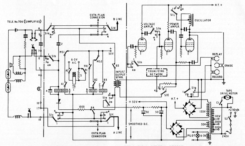
SIMPLIFIED CIRCUIT OF ANSWERING SET No. 1
ASSOCIATED WITH TELEPHONE No. 706
Making a Recording
The selector switch is turned to the "Record" position and connects the
whole of the telephone transmission circuit to the input of the amplifier.
It also switches smoothed d.c. to the transmitter. The user gets normal
telephone speech conditions, including some side-tone, while recording and
he unconsciously adjusts his voice to normal level without the aid of a
volume indicator. The ringing circuit is switched via a 2uF capacitor in the
set in order that ringing current from an incoming call can be applied to
the telephone bell even if the switch is left in the "Record" position.
While a recording is being made there is no connexion between the speech
circuit and the exchange pair. In the amplifier, the selector switch applies h.t. to the bias oscillator, connects the input transformer to a power
amplifier and connects the amplifier output, together with bias current, to
the record/replay head of the tape system. At the same time, bias current is
applied to the erase head to remove the previous recording.
The recording process commences when the "Start" button is pressed. This
action sets the indicator pointer at the beginning of the time scale, and
also operates relay B mechanically. As before, the tape drive motor is
switched on, cycling the tape once until the microswitches are opened; when
this occurs, relay B releases and relay C cuts off the motor.
Checking the Recording
In turning the selector switch from "Record" to "Check", the only circuit
changes are in the amplifier unit where the record/replay head is now
connected to the input of a high-gain voltage amplifier, and h.t. is
disconnected from the bias oscillator. Operation of the "Start" button, as
before, causes the tape to make one cycle during which the recording is
heard in the telephone receiver but, because an attenuator is added to the
amplifier output in this switch position, the recording is 3db or 4db below
the level which is available for transmission to line. By this means the
user is able to hear the message at about the same volume as a local caller
will hear it, and can satisfy himself as to its volume and clarity.
When standard direct-exchange-line service is required, the function switch
is turned to �Off�, disconnecting the mains supply, providing through
circuits from the exchange pair and electrically dissociating the set from
the telephone circuit.
Use of the Answering Set with Multi-Instrument Installations
To avoid complications in the wiring of extension plan and similar systems,
straps are provided in the set so that the exchange line can be intercepted
when the function switch is at "On", while in all other switch positions the
exchange pair is routed straight through the set. In these circumstances, a
separate telephone instrument is provided for recording and checking.
Characteristics of the Record/Replay Amplifier
The recording amplifier can accept peak input signals of about 2 volts
without distortion, i.e. it can accept the maximum speech voltage likely to
be developed in the transmission circuit of a modern telephone; an
equalizing network is included to reduce over-emphasis of sibilants.
The replay amplifier contains a compensating network giving a generally
rising gain/frequency characteristic which tends to offset loss of higher
speech frequencies due to the comparatively low tape speed. The overall
effect gives a substantially smooth frequency response over the range
600-2,200c/s, falling by about 8db at the extremities of the speech range
of 300-3,400c/s.
The speech voltage output to line closely follows the input level from the
transmission circuit of the recording telephone, the variation being of the
order of 2db. The caller thus hears the recorded message at about the same
strength as he would hear the called subscriber if the call were answered
personally.
Power Consumption
The power consumption of the answering set has been kept low - a desirable
feature since the set may be connected to answer calls over a long period
and since the subscriber provides the power. The consumption is
approximately 15 watts in the standby condition and reaches a maximum of 36
watts when a recording is being made.
CONCLUSION
The Answering Set No. 1 caters for those subscribers who require a simply
operated device which, in their absence, will give callers a message saying
where or when they can be located.
ACKNOWLEDGEMENT
The author wishes to thank Sontronic, Ltd., of Edgware for their
co-operation in the development of the answering set.
Pictures
 |
| Answering Set No. 1A/1 |
| |
 |
| Answering Set No. 1A/1 |
| |
 |
| Answering Set No. 1A/2 |
| |
 |
| Answering Set No. 1A/2 |
|