DIAL No. 5 | ||||||||
|
When plastic cased telephones were
first introduced ATE used the Dial No. 5, nicknamed the Dimple Dial, on their
Telephone No. 6.
The dial fingerplate was solid plastic with depression against each number. To turn the dial the use placed their finger in the depression and turned the dial. The ATE Part Number was L11727A and L39977A.
An article taken from the ATE Technical Review
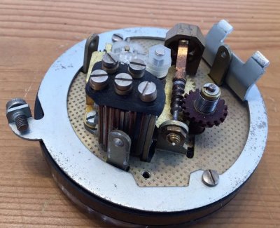
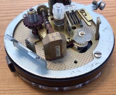
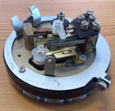
(Page 63) Moulded components are used whenever possible, for example, the moulded base, the combined number ring and finger-plate and the combined nylon pinion and cam for operating the impulse springs. The moulded base is screwed to a circular steel base, which carries the whole of the mechanism. A steel bearing plate provides one bearing of the main spindle which at this point is fitted with an oil-impregnated phosphor bronze liner. A brass bracket, secured to the base by two screws, provides the other bearing for the main spindle. A feature of particular interest is that two brass gear wheels are employed, having a separating washer between and linked together by a tensioned "C"-shaped piano wire spring. One of the wheels is securely fixed to the main spindle and the other is free. A pinion plate, having a stub axle for the combined nylon pinion and cam, is also free 'on the main spindle. When, therefore, the pinion is engaged with the gear wheels and the finger-plate is turned, the pinion plate and pinion are carried round until arrested by a "stop". Further turning of the finger-plate thus causes the pinion and cam to rotate, but this has no effect as the cam is by now out of alignment with the impulsing springs. The cam plate moves backwards during the initial portion of return movement of the finger-plate and is then arrested by the stop, thus causing the pinion and cam to rotate and operate the impulsing springs during the remaining movement. The time taken from the commencement of the return of the finger-plate until the cam plate reaches its stop is calculated to give the required two-pulse delay period before impulsing commences. This action is extremely simple and reliable and, by virtue of the tensioned "C" spring between the two gear wheels, is entirely free from any backlash. The governor worm and wing assembly are of conventional design, the governor weights being of brass. The governor cup is of oil-impregnated phosphor bronze, and thus eliminates the need for lubricating the governor worm bearing. The thrust end bearing is of the captive ball type which has been well proved in service over many years. The governor is driven by a Bakelite worm wheel which forms part of a spring clutch assembly, which enables the clutch pinion to rotate without operating the governor weights during the winding up action. The Type No. 5 is practically noiseless in operation and has given very satisfactory results on life tests, over 3,000,000 operations having been obtained.
L39977A shown below/font>
|
||||||||
Last revised: October 03, 2025FM2 | ||||||||