| A wall mounted Bellset for internal use, generally found in
customers premises. They were always hard wired into the telephone
line. There is no Bellset No. 50E but many confuse this with the
Bell No. 50E. All these
Bellsets are supplied with a capacitor, which is soldered onto the circuit
board.
Bellsets No's 50A to 50D are fixed to the wall with a Bracket, Telephone No. 16.
This is a 'T' shaped
metal bracket, the
same bracket used on 700 type wall phones.

Rear view showing T bracket in place
The cover is plastic and were available in grey and ivory.
The cover is called a Part 1/DCO/763.
To remove the cover on Bellset No's 50A to 50D:-
Grasp the lower edge of the cover and pull toward yourself. The cover
will easily unclip and once it is swung out about an inch then lift the
cover upwards to dislocate the upper clip. Refitting is the same
principle but in reverse.
To remove the bellset from the wall mounting on Bellset No's 50A
to
50D:-
Remove cover as above and then locate the screw fitted centrally at the
lowest part of the bellset. Once the screw is release, then grasp the
bellset at the lower edge and pull towards you. Swing upwards about an
inch and pull the top end away from the wall bracket clips. Refitting
is the same principle but in reverse.
Circuit diagram - N550.
Bellset No. 50A
A standard Bellset (1000ohm bell ringer & capacitor).
Supersedes Bell No. 59A and
Bellset No. 26.
Fitted with Bell No. 59C-1 and Telephone-Unit 1/D93315.
It was superseded by Bellset No. 50C.
Drawing - 93314.
Circuit Diagram - SA/SAW4287.

Bellset No. 50A
Using early style circuit board
Bellset No. 50B
A
Bellset containing a Telephone No. 746 circuit for use with
the
Telephone No. 713. This Bellset Superseded the
Bellset No. 48.
It is fitted with Bell No. 59C-1 and Telephone-Unit 2/D93315.
It was superseded by the Bellset No. 50D.
A Buzzer No. 32C-3 can be fitted to the circuit
board mounting brackets.
Drawing - 93314.
Circuit diagram - SA/SAW4288.
 |
| Bellset No. 50B |
Bellset No. 50C
Standard Bellset for new plan (PST - 4000 ohm ringer & capacitor).
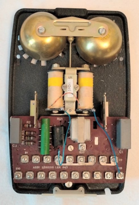
Fitted with Bell No. 59D-1 and Telephone-Unit 1/D93315.
This Telephone-unit was originally the same size as a telephone circuit board
but later on was miniaturised. Both circuit boards are shown below.
Plastic cover in grey or ivory.
Circuit Diagram - SA/SAW4287.
 |
 |
| Bellset No. 50C (cover on) |
Bellset No. 50C (cover removed)
This Bellset shows the small Telephone Unit |

Bellset No. 50C using Telephone-unit 1/D93315
Bellset No. 50D
High impedance version of the Bellset No. 50B for use with Telephone No. 713.
Fitted with Bell No. 59D-1 and Telephone-Unit 2/D93315.
Circuit diagram - SA/SAW4288.
ADDITIONAL INFORMATION
Bellsets No. 50B (Low Impedance bell set for use with hard wired, series connected extension
bell arrangements) are no longer available centrally on BT. Local stocks should only be
used to maintain existing hard wired installations, when local stocks exhaust, faulty Bellsets No. 50B should be maintenance replaced by
Bell No. 50E and system converted to
PST. Existing
serviceable Bellsets No. 50B and 50C may be used for internal shifts.
Click here for the difference between a Bell and a
Bellset
Converting to work in the UK on PST
Connecting a PST line cord to a Bellset No. 50A
or 50B (500 ohm bell coils)
Follow the following instructions:-
- Connect white wire of line to terminal B8.
- Connect red of the line cord to terminal B9.
- Connect green of the line cord to terminal E.
- Remove the link between B2 and B3.
- Insert a 3.3k resistor between B2 and B3.
- Connect blue of the line cord to terminal B3.
Connecting a PST line cord to a Bellset No. 50C
(2000 ohm bell coils)
Follow the following instructions:-
- Connect white wire of line to terminal B8.
- Connect red of the line cord to terminal B9.
- Connect green of the line cord to terminal E.
- Connect blue of the line cord to terminal B2.
Bellset No. 50A


Using later style circuit board
Bellset No. 50B
|