COIN TELEPHONE No. 23 | |||||||
| Engineering name - Coin Telephone No. 23. Marketing name - Payphone 100 mark I. Made by Agifon, their Model 100. Sales Brochure - PHME103 TELECOM INSTRUCTION COIN TELEPHONE No. 23B 1 CONTENTS 1 CONTENTS 2 INTRODUCTION The mode of the CT23B is controlled by a lockable switch. When the "O" symbol has been selected the CT23B works as a normal DEL with access to IDD, STD and all operator services. Calls will meter on the associated exchange meter and the customer charged in the normal manner. Selecting the "P" symbol converts it into a payphone with restricted facilities. In this mode it will accept 2p, 5p, 10p and 50p coins but there is no access to operator services (or any lxx codes) except for '999' calls. The CT23B cannot be used in plan numbers (except Phonesocket where an extension can be added) or on shared service lines.
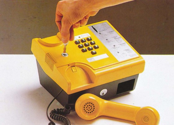
3 GENERAL The line cord is a Cord Connecting No. 4/500 3000 mm which is plug ended at the Line Jack No. 2/7A and at the telephone. The handset cord terminates on a plug and socket inside the payphone to allow for ease of replacement. Above the keypad there is a Credit Display window which consists of a Red Light Emitting Diode (LED) which flashes advising the customer to insert money. The minimum call charge fee is also displayed in this window. The CT23B is provided with a Tone Generator calling device similar to the Trimphone. The CT23 is available in the colours - Yellow, Brown and Stone. The dimensions are 180 mm (height) x 230 mm (width) x, 200 mm (depth) and it weighs 3 Kgs (empty). 4 PRE-INSTALLATION INSPECTION 5 INSTALLATION Stores Coin Telephone No. 23B ... colour Battery Secondary No. 34 Line jack Unit 2/7A Block Terminal 80A NOTE: The lockable mode switch and cash box lock are already fitted on delivery of the CT23B. Mode Switch and Cash Box Key Procedure Cash Compartment/Mode Switch Key Handling The exterior of each CT23B carton will be stamped with a serial number. Enclosed within the carton will be a heat-scaled opaque envelope containing two keys for the cash container and two keys for the mode switch. Associated with this envelope will be a three part card.
The carton should be opened by the Storekeeper or the Maintenance Repair Centre staff, dependant on Area organisation, and the envelope containing the keys be removed. Parts 2 and 3 of the serial number card should then be sent, with the keys, to the Sales Renters Payphone Duty. Part 1 of the card should be kept in the carton for reference purposes only. The Sales Coinbox Duty should store the keys until required. When an AN for a CT23B is issued a serial number should be allocated from the keys in store and noted on the AN. The AN plus parts 2 and 3 of the card should be forwarded to the Installation Control. The card A4488 should be completed in the normal manner and the keys forwarded to the customer by recorded delivery. On receipt of an AN at the Installation Control, the Installation officer should complete parts 2 and 3 of the card. Part 2 should be attached to the AN and given to the Fitter. Part 3 of the card should be forwarded to the Sales Division. The Fitter should present the AN with part 2 of the card to the Storekeeper. The Storekeeper should identify the correct carton using the serial number and issue the CT23B. Fitting Instructions A signalling earth must be provided at the customers premises. Wire Earthing, 9141 /1W should be used to connect the signalling earth to the Line jack Unit of the CT2 3B, via a Block Terminal 80A. IT IS ESSENTIAL TO ENSURE A GOOD SIGNALLING EARTH AND THAT AS FAR AS IS PRACTICABLE THIS WIRING IS NOT ACCESSIBLE BY THE GENERAL PUBLIC. Battery To install the battery:- (i) remove the moulded case. To achieve this loosen the two retaining screws at the rear of the case using a Ringdriver No. 9. When removing the case, gently lift rear of the case whilst easing it forwards. After the case has been removed the battery compartment can be seen at the top left-hand corner of the mechanism compartment. (ii) unclip and lift the processor board. To secure the board in the raised position slide it either to the right or left. (iii) remove the mode switch, this enables the battery to be easily installed. To remove the mode switch unclip the right-hand side of the mode switch bracket. Slide the bracket towards the rear of the case. Lift the switch and bracket out and lay to the side of the telephone. (iv) clip the Battery No. 34 onto the support bracket, see Fig 5. (v) replace the mode switch using the reverse procedure as described in (iii). (vi) release and lower the processor board. (vii) the battery leads are connected to the battery socket which is situated under the key- pad board (Marked PL2/batt). To remove the keypad board just lift up, this will expose the notch which accommodates the battery leads. Replace the keypad board. Cash Compartment Lock Mode Switch Lock (Lock No. 58A) Telephone Number/Minimum Fee Label Minimum Fee Label: - LAB 542A Telephone Number Label: - LAB 542B Fixing CT23B to a Shelf (a) ask the customer to unlock and empty the Cash Compartment, (b) remove the case, (c) remove the mechanism compartment from the cash compartment. Unclip torsion bar, lift off the entire mechanism and put it in a safe place. The cash compartment is now left on its own, (d) screw the cash compartment to the appropriate shelf using two screws placed in the top right-hand and bottom left-hand corners (viewed with the cash box lock to the front). To enable the top right-hand screw to be fitted, the torsion bar supporting collet will have to be removed. Once the screw has been installed replace the plastic collet. NOTE: ENSURE THAT THE POSITION OF THE CT23B ON THE SHELF ALLOWS SUFFICIENT ACCESS TO THE REAR OF THE CASE TO ENABLE THE CASE FIXING SCREWS TO BE REMOVED. (e) replace the mechanism and re-clip the torsion bar, (f) relock the cash compartment, (g) replace the case cover. Fitting a Clasp (Part No. I/DLC/184) to the Rear of the CT23B This can be achieved in a similar manner as described above but instead of screwing to a shelf a clasp is bolted to the rear of the cash compartment using the two knock out holes situated on the rear panel. 6 TARIFF SETTING If at any time during the call the received SPM period exceeds a value "M" the payphone applies a tariff, equivalent to a SPM period, "M" charging reverts to being based on the received SPM Pulse period only if it becomes less than the value "M". NOTE: TO ENABLE THE TARIFF TO BE STORED IN THE CT23B THE BATTERY NO. 34 AND THE EXCHANGE LINE NEED TO BE CONNECTED. Method the following method should be carried out with the case removed and the processor board in the raised position (to gain access to the Tariff Button). NOTE: Because the case has been removed release the gravity switch and check for dial tone. Press and release the tariff button situated on the speech board. Dial tone is replaced by tones to state that the tariff has not yet been set. The tones are: - 1 second of 800 Hz 1 second of 400 Hz repeated 3 times. Pause followed by a continuous tone lasting for 3-8 seconds. At the end of the continuous tone the CT23B is ready for the tariff to be set by using the keypad. The tariff is in the form of 5 digits as follows: - Digit: 1 2 3 4 5 m Rate Minimum Fee (in pence) Unit Fee (in pence) NOTE: If minimum fee or unit fee is less than 10 ensure that two digits are set i.e. 08 or 09. M Rate is represented by pips of tone (400 ms of 400 Hz followed by 600 ms of pause). M = 1 pip (90 secs) = 2 pip (120 secs) = 3 pip (180 secs) = 4 pip (Infinity i.e. no internal timer) Therefore to insert a tariff setting of minimum fee 8p, unit fee 6p and no internal timing the five appropriate digits are keyed i.e. 08064. When valid tariff has been received the new data (in the form of tones) are played back. Then dial tone will be heard and the red LED (minimum fee) will glow. Check of Tariff The information is as follows: - 5p Fee value............... 300 ms of 800 Hz followed by 200 ms pause Example: - For tariff digits 08064 tones heard: - 800 Hz.400 Hz.400 Hz.400 Hz . . . 800 Hz.400 Hz . . . 400 Hz.400 Hz.400 Hz.400 Hz Followed by a continuous tone lasting 3-8 seconds. NOTE: the first tone of each set is always the 5p tone (800 Hz), if applicable. After checking if the tariff information is correct wait approximately 30 seconds and dial tone will be restored. If the tariff information is incorrect after hearing the continuous tone key in the correct tariff figures. Introduced 1981. Requires a Subscribers Private Meter SPM supply and a signalling earth. Superseded in 1991 by the Payphone 190. PAYPHONE 100 Many small businesses would like to provide their customers or visitors with
the use of a telephone but cannot afford to give away free calls, while other
businesses may want to control their staff's use of the telephone. Households
may want to cut down on heavy telephone bills by ensuring everybody pays as they
call.
When it is used as a payphone:-
We hope you will like this new payphone from British Telecom. If you have any
questions - about ordering for example (this payphone will become available in
Autumn 1982 at a rental of around £20 per quarter - this is in addition to
the exchange line rental), please contact:-
Coin Telephone 23A and 23C compared
|
|||||||
Last revised: March 16, 2026FM |