DEVELOPMENT OF TELEGRAPH SWITCHING
| |||||||||||||||||||||||||||||||||||||||||||||||||||||||||||||||||||||||||||||||||||||||
|
A Paper read before the London Centre on the 14th March, 1944, and at other Centres during the Session 1944-45 CONTENTS
1. HISTORICAL
FIG. 1 - THE UMSCHALTER SWITCH This method of switching was adopted in England about the year 1854 by the Electric & International Telegraph Co., the switches being fitted at selected centres including London, Leeds, Manchester and York. Switching was chiefly confined to local lines connected to the particular centre. On occasions local lines were switched to main lines, but generally main lines were never connected together. The use of switching for Morse circuits was abandoned when the Government took over the British telegraphs in 1870. Of the private telegraph companies taken over by the Post Office, several had developed private wire services to renter's offices. One of these, the Universal Private Telegraph Co., had its largest installation at Newcastle-on-Tyne, comprising some thirty-five lines and instruments, the type of instrument employed being the Wheatstone A.B.C. which required no particular skill to operate. About 1874, owing to development, additional space was required to accommodate some sixty lines and instruments. As an alternative to this, a switch of the "Umschalter" type was installed, which enabled the instruments at the head office to be reduced to fifteen. In order to provide intercommunication facilities between any two renters, an A.B.C. indicator was connected permanently in each line to provide supervisory facilities. During slack periods the lines were connected to earth via a bell-set in order to provide an audible alarm. At other centres such as Glasgow, Sunderland .and Swansea similar systems were installed. About 1884 these systems were ousted by the development of the telephone. 1.2 Telegraph Concentrators A special type of concentrator where incoming calls were automatically fed to the various instrument positions was tried out at a provincial office, but its use was never extended. For some years prior to 1935 there was a serious and progressive decline in telegraph traffic which resulted in a considerable reduction of the number of long distance circuits and the conversion of a large number of local circuits to telephone-telegram working. In 1935 the outlook for telegraphs became considerably brighter, as a reduction in telegram rates resulted in a large increase in traffic. The Post Office was, however, well prepared for meeting the increased traffic requirements as a result of the following developments:-
A number of telephone-telegram circuits were converted to teleprinter working and although the traffic carried was too heavy for telephone-telegram working it was not sufficient to justify the continuous attendance of an operator at one circuit. It therefore became essential to re-introduce some form of concentration, not only for local but for other circuits during their lightly loaded periods. To meet these requirements the ancillary type of concentrator was introduced. The original type of telegraph concentrator had lines and instruments connected to one switchboard, an operator being employed to deal with calls to and from the several instrument positions connected to it. For the ancillary, a switchboard is fitted at each teleprinter position, thus each operator is given access to all circuits connected to a particular ancillary. The number of operating positions for a given number of lines depends entirely upon traffic requirements. 1.3 London Intercommunication Morse Switching Scheme Each office was designated by a number, and street lists were provided showing the offices to which messages for every address within the Metropolitan area should be sent. In the Central Telegraph Office itself, the local instruments were divided between the different floors, in order to facilitate the circulation of telegrams. Each particular set of instruments on a particular floor was given a special code. For example those instruments installed on the 2nd Floor had the code TSB and all messages to and from towns with telegraph circuits terminating on that floor were dealt with by those instruments. The circulation lists issued to each office indicated to which section of the C.T.O. messages should be transmitted. Separate instruments were allocated for the reception and transmission of telegrams. In the design of the switchboard the principles of telephone switchboards of the multiple type were followed, with central battery working suitable for telegraph purposes. The board was made in 12 sections, each section consisting of three operator's positions, with two panels per position, the full multiple occupying six panels. At the beginning and end of the suite a dummy section was installed to give the end operators access to the full multiple.
The answering field on an operator's position was provided with lamp signalling, but the engaged signal in the multiple was provided by means of an indicator with a white disc. Each cord circuit comprised two re-transmitting relays, a clearing relay and lamp and an answering and calling key (telephone type). A Morse speaker circuit was provided on each operator's position and could be interpolated into any cord circuit by the operation of the relevant answering and calling key. The apparatus at out-offices and at the Central Telegraph Office consisted of a Morse key, polarised sounder and a special plunger type key and indicator, the use of which was to give calling and clearing signals to the switchboard and to give an indication when calls were answered and cleared. This switching system was worked until 1922. Under normal loads traffic was dealt with fairly expeditiously, but the heavy seasonal increases caused considerable congestions and delays, due to the line provision not being adequate for maximum traffic loads. It is doubtful whether, under the conditions of hand speed Morse signalling, such a system could ever have justified itself economically. 1.4 Automatic Switching 1.5 Continental Systems The German administration employed an automatic switching network for the use of private renters, worked on a teleprinter basis, with linkages from Germany to several European countries. Connections to subscribers in Holland were received at Amsterdam on a D.C. basis and converted to A.C. (1500 c.p.s.) for transmission to subscribers over the normal telephone network on a Telex basis. Connections for England were similarly converted at Amsterdam and passed over normal telephone circuits. Calls for Germany were converted at Amsterdam from 1500 c.p.s. to D.C. With the extension of multi-channel voice-frequency working from this country to France, Belgium, Holland and Germany, a teleprinter switching system for private renters was in the process of being set up, but the outbreak of war necessitated the abandonment of the project. 1.6 Development of Switching Facilities for Teleprinter Private Wire
Services In order to permit of the switching of long telegraph circuits for teleprinter working, it is essential that the various links in a connection should be made up of stable high grade circuits such as are provided by multi-channel voice frequency telegraph systems. At the beginning of 1939 the growth of the inland voice frequency telegraph network had been considerable and between London and certain provincial centres one or more 18-channel systems were provided entirely for teleprinter private wire services, in addition to a large number of channels appropriated in public service systems. The availability of suitable circuits made it possible to consider the introduction of switching on teleprinter private wire circuits, and development work was commenced about 1937. This work was considerably accelerated as a result of the increased defence programmes which gave rise to requests from the Services and Government Departments for teleprinter intercommunication between widely separated centres. In the physical design of switchboards, telephone practice was naturally followed as far as practicable, but special problems arose due to the need for accommodating a teleprinter on the operator's switch section. The basic signalling arrangements presented peculiar problems, and some of the factors influencing the circuit design are discussed in the following sections.
2. BASIC FACTORS INFLUENCING THE DESIGN OF A TELEPRINTER SWITCHING
SYSTEM The teleprinter uses a 5-unit code for the signalling of each character,
and to enable operation on a start-stop basis, a start signal precedes the
5-unit code and a stop signal completes the transmission of each character.
The five code units, each known as an "element of signal," are of equal
duration. The duration of the start signal is equal to one code unit while
the duration of the stop signal has a minimum duration of 1.5 units. Thus
the minimum duration of a complete signal combination for a teleprinter
character is equal to 7.5 units and for a Teleprinter No. 7 this is
equivalent to 150 milliseconds (ms). Each code unit may be one of two
conditions known as "Mark" or "Space." These expressions are derived from
the days of Morse when signals were recognised by definite marks and spaces
on a paper slip. The significance attached to these expressions when
referred to teleprinter signalling, is that the rest condition of the
teleprinter corresponds to "mark while the start signal is "space." A mark
signal following the 5-unit code operates as the stop signal. The five units
of the code are called either "mark" or "space," depending whether they have
the same sense as the signal during the rest condition, or the start signal.
On the majority of present-day telegraph circuits employed in Great Britain,
and all circuits suitable for use in a switching system, the teleprinter is
arranged to transmit -80V for mark and +80V It is desirable that the design of a switching system should cater for the possibility of expansion on a national basis and provide for complete intercommunication between all subscribers. Also for flexibility and economy in the provision of junction circuits it is essential to be able to set up calls which involve through switching at a number of switching centres. The line transmission limits are therefore a major factor in design. It will be appreciated that the limitations imposed on the make-up of circuits must be more severe than for point-to-point circuits, as any circuit may be linked with any other circuit in the system. Furthermore it may be necessary to impose special limits to obtain satisfactory operation of supervisory circuits. The factor which limits the satisfactory transmission of teleprinter signals between two points is the total distortion which arises in the transmission of the signals over the circuit. The distortion due to the line is dependent on the electrical characteristics of the transmission circuit and the magnitude of any interference currents which may be present. Satisfactory teleprinter working is possible, however, so long as the total distortion which occurs during the formation of signals at the transmitter and their subsequent transmission over the line is less than the margin of the receiving teleprinter. The fundamental characteristics of telegraph transmission and the factors which determine the limits for satisfactory working have already been treated in other papers and reference should be made to these for fuller information. The transmission standards adopted must include a factor of safety to ensure satisfactory operation of teleprinter circuits under average maintenance conditions allowing for slight inaccuracies in the adjustments of teleprinters, lines and associated equipment. For the private wire teleprinter manual switching network the transmission standards have been established on the basis that on any call the connection shall not contain more than four V.F. channels in tandem and any physical links or extensions from the V.F. channels are less than 10 miles in length and have negligible distortion. When the connection contains a physical link longer than 10 miles, the permissible number of V.F. channels is reduced to three and the permissible number of physical links in excess of 10 miles is two. In physical circuits over 10 miles the maximum permissible length for satisfactory teleprinter working is determined by the characteristic distortion of the circuit (which is dependent upon the KR of the line) and fortuitous distortion arising from interference from adjacent circuits. The practical limits used, therefore, take account of these factors and vary, depending upon whether the circuits are worked simplex or duplex, and whether one or two telegraph circuits are operated in the same cable quad. For public telegraph circuits increased limits may be obtained by the use of two loop simplex working. Undoubtedly the biggest single factor which made the introduction of telegraph switching possible was the use of V.F. channels for the provision of telegraph circuits. These provide a standard of transmission and stability of service over long distances greatly superior to that possible using direct current transmission links and in addition give the following advantages:-
The signalling arrangements employed in manual teleprinter switchboards in use for private wire teleprinter switching services will now be described.
3. SIGNALLING AND CIRCUIT ARRANGEMENTS EMPLOYED IN MANUAL TELEPRINTER
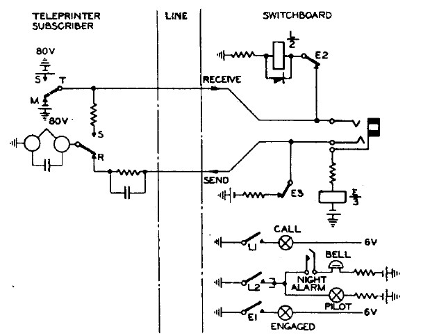
SWITCHBOARDS The switchboard operator answers the call by inserting the answering plug of a cord circuit into the calling line jack. An earth is then applied from the sleeve of the plug and bush of the line jack to a line cut-off relay E which then operates. Contact E1 lights a red engaged lamp, contact E2 disconnects the call relay from the receive line, while contact E3 disconnects the continuous marking current from the send line, the marking current now being replaced by that from the switchboard operator's teleprinter and answer cord circuit. With large multiple type switchboards a free line signalling system is employed instead of line engaged lamps, and contact E1 then disconnects the Free Line Signalling (F.L.S.) lamps of the calling circuit and completes a circuit for the F.L.S. lamps of the next free line in the group. The reason for the choice of a non-locking call relay is to overcome the difficulty which would otherwise occur from false calls produced by line interruptions on V.F. channels. With this arrangement V.F. interruptions normally produce either a transient flash, which is ignored by the operator, or a permanent glow which indicates a prolonged interruption, and is immediately reported as a fault condition and the circuit is plugged up.
Fig. 2 - TELEPRINTER SWITCHBOARD - TERMINATION OF TIE SUBSCRIBER'S LINE
FIG. 3 - TELEPRINTER SWITCHBOARD - CORD CIRCUIT CLEARING ARRANGEMENT To operate the clearing relay, it is necessary to transmit a spacing signal continuously until a reverse charge, positive to earth, is given to the condenser. Then, upon restoration of the normal marking signal in the line, the surge current through the rectifier to charge the condenser negatively to earth is sufficient to operate the clearing relay. Operation of the relay removes the short circuit from its locking coil which then holds. Referring to Fig. 3, CLA and CLC are the clearing relays for the answering and calling cords respectively, both relays being 3000 type. When the calling subscriber clears CLA operates, contact CLA1 removes the short circuit from the locking coil, which then holds in series with the E relay of the line to -80V. Contact CLA2 completes the circuit of the white answering supervisory lamp, whereupon the switchboard operator withdraws the answering plug from the line jack, the holding circuit of relay CLA is thus broken and the clearing circuit reverts to normal. When a switched connection is established through several switchboards, the clearing signal is received simultaneously by each switchboard operator, so that through clearing is given. The operation of the clearing circuit provided on the calling cord is similar. The characteristics of the clearing circuit are such that with relays in standard adjustment it requires a minimum period of 200ms. of spacing signal for operation under the most favourable circumstances, i.e., when the clearing signal is received from ±80V over a line having negligible resistance. On the other hand for operation under the most adverse conditions, that is when the clear is received over a line of maximum resistance, a period of not less than 3secs. of continuous spacing signal is required. For the purpose of sending a clearing signal all teleprinter subscribers' tables are fitted with a non-locking key (connected in series with the send line) which, when operated, transmits a continuous spacing signal.
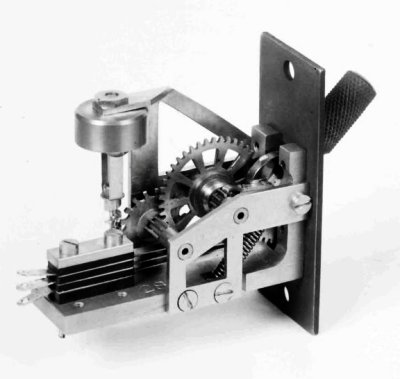
FIG. 4 - DELAYED ACTION LEVER - TYPE KEY (EXPERIMENTAL MODEL) Switchboard operators' positions are provided with a press button to give a clear when required on junction circuits to other switchboards. Operators are instructed to depress the clearing key for five seconds, to make certain a sufficiently long signal is always given to ensure satisfactory operation of supervisory signals. To simplify the operating procedure a delayed action lever time key has been recently developed for clearing purposes, which can be preset to give a spacing signal of the requisite duration. The operator simply depresses and then releases the key, which restores to normal under the control of a standard telephone dial governor. Fig. 4 illustrates, in its experimental form, the key which can be fitted to the present standard teleprinter table equipment. 3.3 Recall Facilities 3.4 Answering and Calling
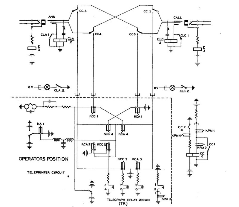
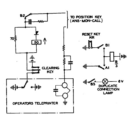
FIG. 5 - TELEPRINTER SWITCHBOARD - CORD CIRCUIT AND OPERATOR'S POSITION EQUIPMENT A position key which is common to the operator's position enables the operator's position circuit to be connected to either the answering or calling side, and in the normal position of the key the operator's teleprinter is connected to monitor the cord circuit. Normally the cord circuit is connected tip to ring via contacts of the switching relay CC. This provides a direct transmission path with negligible transmission loss from the send to receive lines of connected circuits. To answer a call the answering plug is inserted into the jack of the calling line, the position key KCA Js operated to answer and the cord circuit key KPM is operated. The operation of KPM energises the switching relay CC which operates and locks via the "X" contact CC2. Contact CC1 connects an earth to the common point of battery supply to the other cord circuit CC relays, so that these cannot be operated until the cord circuit already in use is restored to normal - thus preventing two cord circuits being connected together. Contact CC4 connects the send line of the calling circuit to the operator's teleprinter transmitter, while CC3 connects the receive line of the calling circuit to one coil of a telegraph relay TR. A second coil of this relay is connected to the operator's teleprinter transmitter, and the relay is also given a permanent spacing bias. The currents controlling the relay TR normally cause it to mark, but if either the calling subscriber or the operator transmits, the relay repeats the signals to the operator's teleprinter. Thus it will be seen that a simplex connection with local record facilities is established between the caller and the operator's teleprinter. The switchboard operator teleprints the call sign of the switchboard, whereupon the caller will teleprint the details of the connection required. The operator then inserts the calling plug into the jack of the line required and signals "K" or "THRU" depending whether the connection has been completed to a teleprinter extension or extended over a junction line to another switchboard for completion of the call. In the former case the caller operates the WRU key to confirm correct connection and then proceeds, whilst in the latter case he calls the second switchboard as before. The first switchboard operator will immediately restore the cord circuit key to normal thus releasing the switching relay CC and completing the through connection between the tip and ring of the answering and calling plugs, via the CC relay contacts. As the final operation the position key will be restored. It is important that the operation and restoration of the cord and position keys should be in the order described, otherwise the telegraph relay will operate to space and cause the operator's teleprinter to race. It is perhaps of interest to mention that the cord circuit facilities contemplated originally were that the parent switchboard operator should handle the call to completion and verify correct connection to the required party before switching the caller through. For this reason the cord circuit incorporates the facility, whereby all signals exchanged between the operator and the called party are repeated by the telegraph relay in the position circuit, to the operator's teleprinter and also to the calling subscriber. The calling subscriber's receive line is disconnected during this stage of the connection to prevent interference, but the caller is able to note the progress of the call at all stages. 3.5 Monitoring The monitoring circuit arrangements introduce a small transmission loss in the cord circuit but the effects are not appreciable, and in any event, as monitoring is usually only necessary at the termination of a call, and when a single clear only has been obtained, the transmission loss introduced is of small consequence. 3.6 Duplicate Connections Should a number of operators answer a call simultaneously, their transmitters will be connected in parallel to the send line of the calling subscriber. The first operator to teleprint will connect +80V to the common connection during the start signal and spacing elements of a character, and a heavy marking current will flow from the transmitters of the other position teleprinters to this battery. The respective A relays on each of these positions will therefore operate and contact A1 will complete the circuit for relay B which operates and locks via contact Bi. Contact B2 disconnects the teleprinter transmitter from the circuit and B3 causes the duplicate connection lamp on the position to glow. Thus the first operator to teleprint to the calling line automatically cuts off any other operators connected to the line. These operators will receive an indication by means of the duplicate connection lamp and will take down their cord and depress the duplicate connection reset key KR which disconnects the hold current of relay B which releases and restores the position circuit to normal.
FIG. 6 - TELEPRINTER SWITCHBOARD - DUPLICATE CONNECTION CIRCUIT 3.7 Broadcasting Facilities
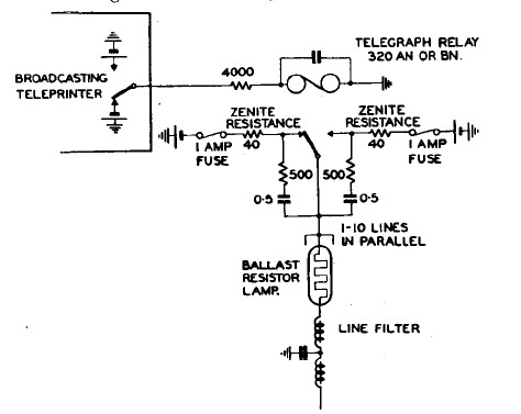
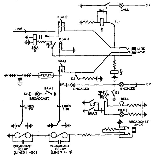
FIG. 7 - TELEPRINTER BROADCAST CIRCUIT It is of interest to mention the factors which have determined the choice of the circuit components used. The first is that when ±80V is transmitted into 10 lines in parallel the surge current may rise to 3 amps due to the capacities of the line and the low pass filter which is fitted in each line to prevent interference to adjacent telephone circuits. This will produce severe sparking at the relay contacts if bounce occurs and give rise to rapid contact build up until finally the contact gaps become choked, producing a short circuit and welding of the contacts and tongue. To reduce the surge currents and increase contact life, protective resistances are fitted in the battery feeds to the contacts, but as it is necessary, from the point of view of signal distortion, to limit the voltage drop which occurs to a minimum, it is necessary to keep the protective resistances as low as practicable. They should, however, be such that they will safely carry a 'short circuit current if this occurs and limit it to a value of 2 amps which is insufficient to produce welding of the contacts. The battery fuses are rated to blow under this condition. Sparking at the contacts is reduced to a minimum by a double spark quench circuit which consists of a 0.5uF condenser and 500ohm connected from the relay tongue to each contact this arrangement is found to be more satisfactory than a single quench circuit from tongue to earth. In order that faults occurring on one line shall not interfere with broadcast reception on the remaining lines, a ballast resistor bulb is fitted in series with each line. The characteristic of this resistor is 100 ohms when cold, rising to 700ohms when earthing a current of approximately 100 milliamps. Thus if a full earth occurs on one line it increases the load on the relay by approximately 0.1amp, but the increased distortion of signals which occurs on this account is not sufficient to prevent satisfactory reception on the remaining circuits and a visual indication of the earth fault is given by the resistor bulb glowing. Various broadcasting facilities are required by private wire renters, but the broadcast circuit is basically always the same and is as described in the foregoing. The differences between the various systems in use arise due to different supervisory requirements and the flexibility for partial broadcasts. Lines are sometimes set up permanently for broadcast reception from a central office and for this type of network a standard broadcast relay panel is available which is suitable for wall or rack mounting and which caters for broadcasting to 10 lines. The broadcasting teleprinter is connected to the coils of the broadcast relay of one of these panels which is situated at the most convenient point from which lines can radiate to the receiving teleprinters direct or to additional broadcast relays at other centres from which other lines radiate. Any number of receiving teleprinters can be connected to a broadcast network of this type provided that where more than 10 lines are to be connected in broadcast at any point in the system then a number of broadcast relays will be connected in series so that only 10 lines are connected from the transmitting tongue of any one relay. Usually supervisory signalling is required in a broadcast network to enable acknowledgement of reception to be given and a broadcast switchboard is then used. One type of switchboard used for this purpose but suitable for short physical lines only, has already been mentioned, but this type is now obsolescent due to demands for intercommunication facilities in addition to broadcasting. As a result all intercommunication teleprinter switchboards either incorporate facilities for broadcasting as a standard arrangement or may be worked in association with a broadcast switchboard. A typical circuit arrangement in principle is shown in Fig. 8. The line is connected to the switchboard multiple via a broadcast key on the switchboard face equipment, and in the normal position of the key the line is connected to the switchboard line calling equipment as already described. One or more groups of broadcast relays are provided, the coils of which are wired to broadcast jacks in the multiple; only a single group of relays, and associated line keys and broadcast jack, are shown in Fig. 8.
FIG. 8 - TELEPRINTER SWITCHBOARD - LINE TERMINATION WITH BROADCASTING FACILITIES
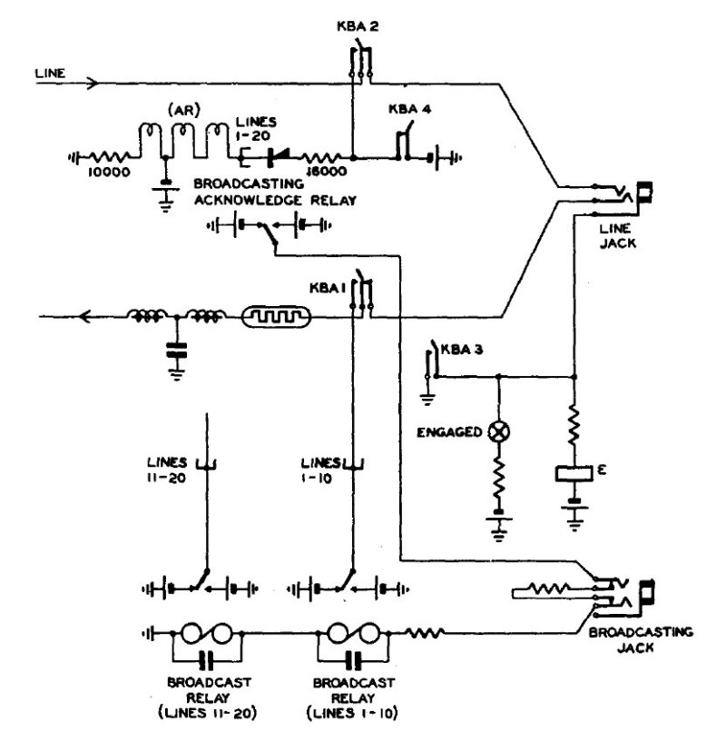
When the broadcast transmission is completed the broadcasting subscriber and all receiving operators will transmit a normal clearing signal. The supervisory clearing circuit of the switchboard answering cord is therefore operated and the broadcast acknowledgement relay BRA in each line connected to the broadcast will operate and lock via contact BRA2. Contact BRA1 completes a circuit for an acknowledgement lamp associated with the line broadcast key and contact BRA3 causes the switchboard pilot lamp to light and also ring a bell if required. When an acknowledge lamp signal is received the switchboard operator restores the broadcast key for that line to normal. Finally, when all acknowledgements have been received the switchboard operator withdraws the calling and answering plug of the cord circuit. It will be seen from Fig. 8 that when a line key is operated for broadcast reception, an earth is applied to operate the line cut-off relay E and also prepares the locking circuit for the broadcast acknowledge relay. Contact E1 lights a red engaged lamp above the line broadcast key in addition to operating an engaged lamp or stepping the F.L.S. in the switchboard multiple appearance of the line. For certain forms of broadcast traffic it is essential to receive a printed acknowledgement of reception. This involves the switchboard operator in connecting each receiving line in turn to the broadcasting subscriber and when a large number of lines are involved this imposes a prohibitive load on the operator. For such traffic the normal broadcast acknowledgement circuit can be modified to enable printed acknowledgements to be given without the intervention of the switchboard operator. This is done by the circuit arrangement shown in Fig. 9. Immediately the broadcast transmission is completed the broadcasting subscriber sends the call sign of each line in turn and upon receipt of this signal the line teleprints an acknowledgement. The acknowledgement signal operates the telegraph relay AR which repeats the signals to the broadcasting subscriber. When an acknowledgement has been received from each line the broadcasting subscriber clears in the normal manner and the switchboard operator then restores the line broadcast keys and takes down the cord circuit.
FIG. 9 - TELEPRINTER SWITCHBOARD - BROADCAST ARRANGEMENT FOR PRINTED ACKNOWLEDGEMENTS
4. TYPES OF SWITCHBOARDS IN USE FOR TELEPRINTER PRIVATE WIRE SERVICES 4.1 The Switchboard Teleprinter No. 9 An installation consists of the following equipment, viz:-
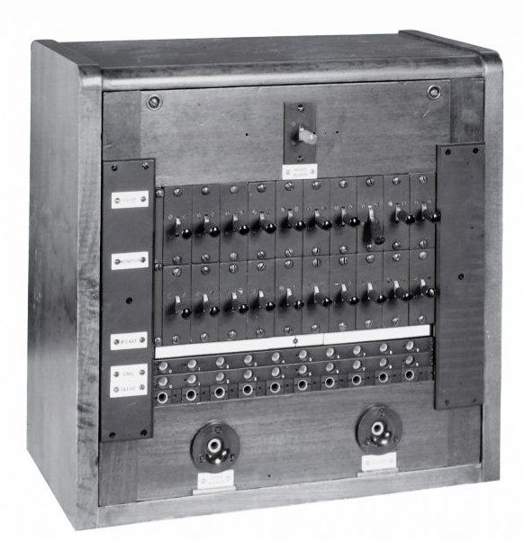
FIG. 10 - 24-POSITION TELEPRINTER SWITCHBOARD No. 9, HAVING SPECIALLY EQUIPPED
C.T.S. FOR BROADCASTING (SHOWN TO THE FAR LEFT) The design of the switchboards follows normal telephone practice, except that in order to accommodate the operator's teleprinter under the keyshelf a special frontal design has been necessary.
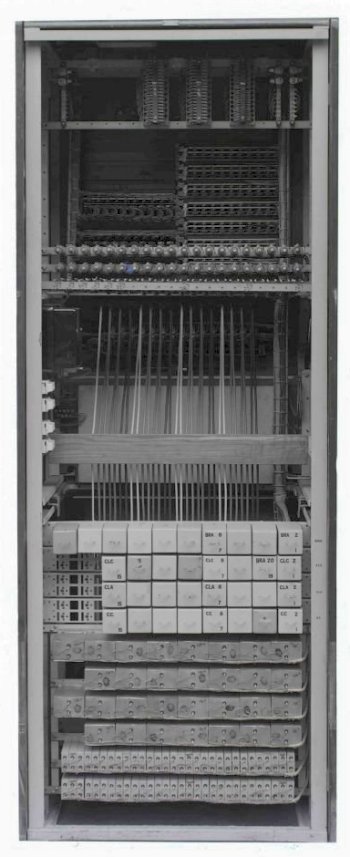
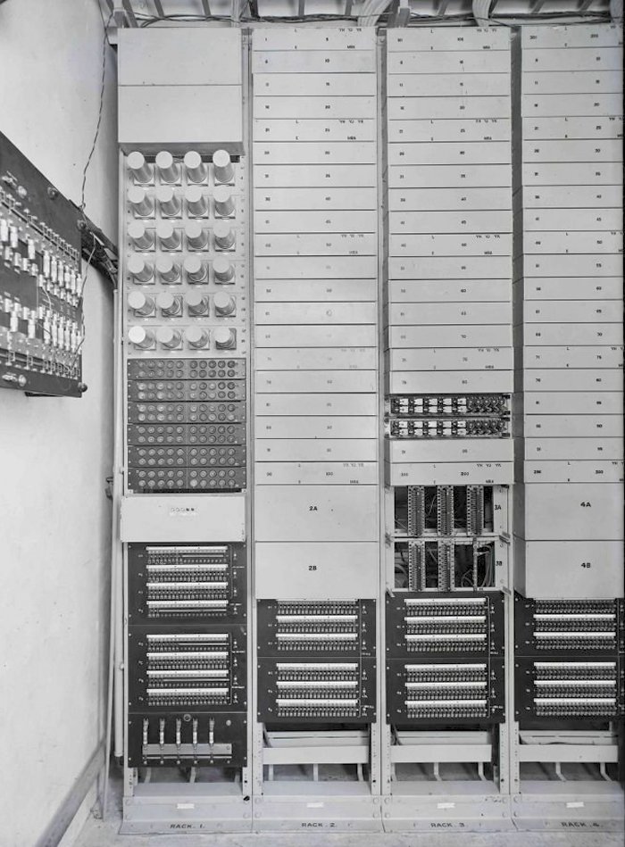
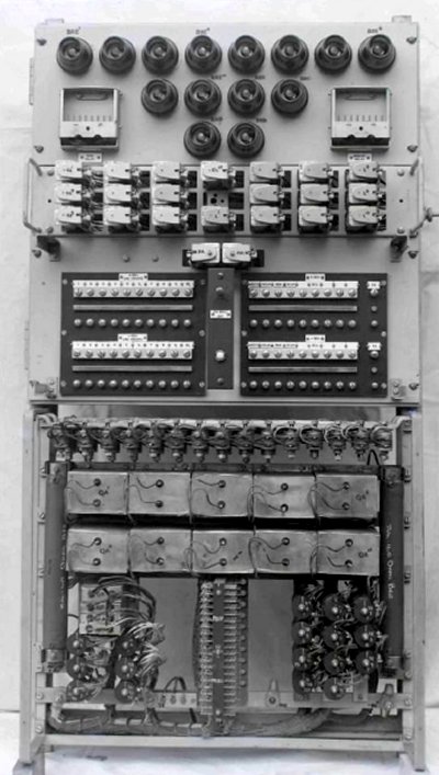
Each section which is known as a Switchboard Teleprinter No. 9 comprises an operator's position and is equipped with two jack panels. The multiple is used for both calling and answering on an ancillary basis and has a capacity of 140 lines/panel, so that with a 3-panel multiple the maximum number of lines is 420. A 4-panel repetition can be employed, and the multiple capacity is then 560 lines. This arrangement, however, has the disadvantage that access on the last operator's position is restricted. Free line signalling is provided on all lines, the first free line in each group being indicated by a lamp glowing behind a green stile strip. The lines are terminated on the switchboard panels in strips of 20 arranged with a call lamp below and an F.L.S. lamp and designation label above each strip. The keyshelf, which is mounted immediately below the line panels, slopes downwards towards the operator and is hinged to facilitate maintenance work. The keyshelf accommodates 15 cord circuits each consisting of one answering and one calling cord each with an associated supervisory clearing lamp, and one "Print and Monitor" key per cord circuit. An "Answer-Monitor-Call" key common to the position is fitted on the right-hand side of the keyshelf together with a "clearing" press button. On the left of the keyshelf is a duplicate connection lamp with a press button reset key. The operator's position teleprinter is a "No. 7B Tape" mounted on a sliding shelf below the keyshelf. The printing position is illuminated by a lamp and an "end of line" red lamp is provided to indicate, when transmitting to a subscriber, the end of a line of printing on a page machine. Both lamps are fitted below the keyshelf. The motor power socket and switch, and instrument jacks for the position teleprinter are mounted on the vertical panel behind the operator's teleprinter. The cord circuit equipment of each position is mounted in the back of the switchboard, which also accommodates a miscellaneous tag block and bars for termination of the rack and signalling earths, as shown in Fig. 11. Additional blocks are provided in the C.T.S. for the termination of ±80V and 6V supplies and monitoring relay wiring from the rack equipments. In addition, cables from the miscellaneous blocks in each switchboard terminate on these blocks. 4.1.1. Apparatus Racks 4.1.2 The Common Equipment Rack
All rack wiring is terminated on connection strips at the
top of the rack from which cables run to the switchboard C.T.S.
4.1.3 The Line Equipment Racks The line jacks and the call and F.L.S. lamps in the switchboard multiple are cabled to the I.D.F. and so by suitable jumpering any line may be connected to any multiple appearance and any line appearance with any line equipment. Thus full flexibility is obtained. The F.L.S. arrangements required are obtained by making suitable straps on a connection block at the middle of the rack. The maximum number of lines in one F.L.S. group is limited to five and where more than five lines exist on one route they are split into groups of five each for F.L.S. purposes. 4.1.4 The Miscellaneous Equipment Rack 4.1.5 Power Supplies The battery capacities may be designed to ensure continuity of service for any reasonable period of mains failure. 4.1.6 Alarms 4.2 The Switchboard Teleprinter No. 14 The line broadcast keys are, mounted together with their associated engaged and clearing lamps in a special panel fitted as an extension to the keyshelf of the C.T.S. of the No. 9 switchboards, as shown in Fig. 10. The wiring from the broadcast panel terminates on blocks in the C.T.S. and is then cabled to the miscellaneous equipment rack and I.D.F. for jumpering to the appropriate lines. The clearing and broadcast relays and other circuit equipment is mounted on the miscellaneous equipment rack. The two broadcast jacks are fitted in a miscellaneous jack strip on the first switchboard operator's position and all requests for broadcast transmissions are passed to this operator for completion. When a request for a broadcast is received, the switchboard operator throws the keys of the lines to be included to Broadcast Position 1 or 2 whichever is free. This disconnects the line from the switchboard multiple, steps the F.L.S. lamp, and lights an engaged lamp associated with the line 'broadcast key. It should be noted that if a line is engaged at the time on a normal through call, then the engaged lamp for the line will glow on the broadcast panel. When the broadcast keys have been operated, the operator extends the caller to Broadcast jack 1 or 2 as appropriate, signals "K" and restores the cord circuit and position keys to normal. Upon completion of the call, all subscribers clear in the normal manner, a broadcast clearing lamp is lighted for each line and a clear is received on the answer cord, whereupon the operator restores the broadcast keys and takes down the cord circuit. 4.3 The Switchboard Teleprinter No. 8
An installation consists of the following equipment:-
The construction of the switchboard is almost identical with the switchboard teleprinter No. 9. The face equipment is, however, different from the No. 9 switchboard and consists of two panels, of which the left hand accommodates the line appearances and the right is equipped for broadcasting. The broadcast panel is, however, only equipped on the first operator's position and is used by both operators. The line multiple is used for both answering and calling on an ancillary basis and the lines are terminated in strips of 10 arranged so that above each line jack appears a calling lamp (white), an engaged lamp (red) and a designation label. The broadcast panel is equipped with two strips of 10 keys each, arranged so that above each key is an engaged lamp (red), a broadcast clearing lamp (green) and a designation label. A miscellaneous jack strip is provided at the bottom of the panel and accommodates two broadcast jacks and test jacks, the latter for use in connection with cord circuit tests. The keyshelf and operator's teleprinter equipment is identical with that provided on a switchboard teleprinter No. 9 except that a duplicate connection facility is not provided and a test cord is fitted. The test cord is wired to two milliamrneters fitted above the switchboard panels and is used to check the send and receive currents in the lines and currents in the broadcast relays. The test jacks used in conjunction with the milliammeters enable the cord circuits to be checked. All cord circuit relay equipment is mounted in the rear of the switchboard and two tag blocks are provided for the termination of wiring from the broadcast panel and one block for miscellaneous leads. Earth bars for rack and signalling purposes and an insulated 6V lamp return bar are provided and cabled direct to similar bars on the equipment rack. 4.3.1 The Equipment Rack
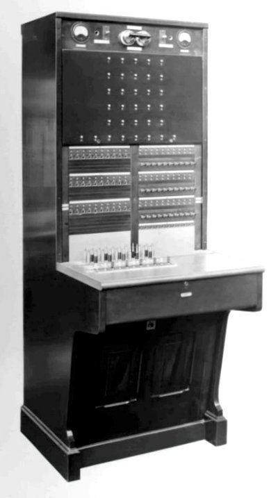
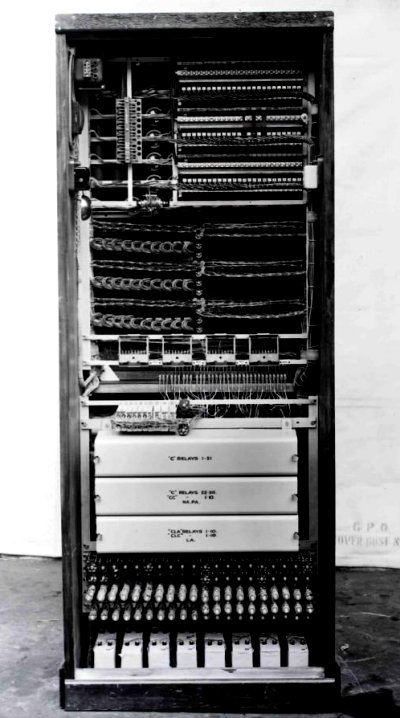
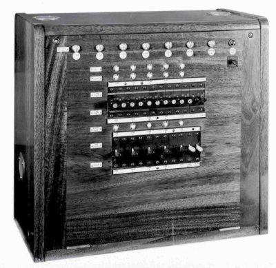
All rack wiring is terminated on connection strips at the top of the rack from which cables are run to the I.D.F. for the line circuits (five wires T, R, S, C and E per line) and to the switchboard for miscellaneous leads. The switchboard line jacks and their associated call and engaged lamps are cabled to blocks on the I.D.F. and the broadcast connections. Thus by suitable jumpering any line may be connected to any line equipment and multiple appearance, and any selection of 20 circuits may be connected for broadcast reception facilities. 4.3.2 The Miscellaneous Equipment Rack Where the amount of miscellaneous equipment is small, however, a wall-mounted rack may be used. 4.3.3 Power Supplies 4.4 The Switchboard Teleprinter No. 13 The switchboard is shown in Fig. 15. It is a floor mounted switchboard and is self-contained except for the power supply and the operator's teleprinter, which is a standard teleprinter instrument table equipped with a No. 7B page or tape machine. The switchboard installation is therefore simply and quickly installed and has proved to be one of the most popular types of board in use at present. The switchboard face equipment comprises a left-hand panel which accommodates the 30 line jacks in strips of 10 and having a white call lamp, red engaged lamp and a designation strip above each ; and a right-hand panel for broadcasting and test facilities. The right-hand panel accommodates three strips of 10 broadcast keys and above each key is a green broadcast clearing lamp, a red engaged lamp and a designation label. A strip of miscellaneous jacks is mounted beneath the broadcast panel and includes a broadcast jack and three test jacks for cord circuit tests. Above the line and broadcast panels is a "broadcast failure" display panel which gives a visual indication of failure of a broadcast transmission to any line due to an earth fault. At the top of the switchboard are mounted a Send and Receive milliammeter, a 6V A.C. - D.C. changeover switch, a fuse alarm lamp and bell off key, and a pilot calling lamp with night alarm key. The switchboard keyshelf is of orthodox telephone design as the operator's teleprinter is not accommodated on the switch section. It contains 10 cord circuits and one test cord used for line testing. Each cord circuit consists of one answering cord and one calling cord, with a supervisory lamp associated with each cord; and one "Print and Monitor" key per cord circuit. An "Answer-Monitor-Call" key common to the position is mounted on the right-hand side of the keyshelf. All the keyshelf equipment is displaced to the left so as to be most readily accessible to the operator whose position teleprinter is fitted adjacent, and to the left of the switchboard. The operator's clearing key is that fitted on the teleprinter table.
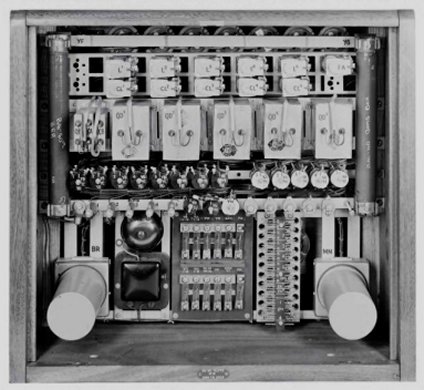
A rear view of the switchboard is shown in Fig. 16, which indicates the assembly arrangements for the various lines and common equipment. It includes a 6V mains transformer for the lamp signalling supplies and alarm type fuse mountings for the ± 80V and 6V supplies. All external connections to the switchboard for incoming lines and the operator's teleprinter are terminated on a tag block. The 80 + 80V supply for signalling and the 160V for the operator's teleprinter motor are derived from a Westat rectifier. If continuity of service under mains failure conditions is essential then an 80 + 80V floating battery is used and the 6V supply is also derived from a rectifier with a floating battery. 4.5 The Switchboard Teleprinter No. 15 The cord circuits are loose double-ended cords wired tip to ring and are hung on a hook at the side of the board until required for use. Fig. 17 shows a face view of the switchboard, the front panel of which is hinged to give access for maintenance, and Fig. 18 shows the rack equipment. An 80 + 80V supply is required for operation of the switchboard and is obtained from a Westat rectifier.
FIG. 17 - SWITCHBOARD TELEPRINTER No. 15 The circuit operation of this switchboard is slightly different from those already described for other types, although the basic calling and clearing circuits are standard.
The lines terminate on the switchboard line jacks with an associated calling relay, but in addition a clearing relay is connected permanently to each line. The connection of a line to its jack appearance is via the contacts of a "Print and Monitor" key and a "Broadcast" key. The position teleprinter is connected through a switchboard jack to contacts of the "Print and Monitor" keys of lines 1 to 10 in series. To answer a call, the "Print and Monitor" key of the calling line is operated to "Print" and this connects the operator's teleprinter in simplex communication with the caller. Details of the required connection are received and the call is completed by patching a double-ended cord from the line jack of the calling line to that of the required party. The operator transmits "K" to the caller and then restores the print key in readiness for the next call. To monitor an established connection the "Print and Monitor" key of either of the connected lines is operated to "Monitor," and this connects a telegraph relay in leak from the send and receive lines and the relay repeats signals passing to the operator's teleprinter. To set up a broadcast, the calling subscriber is answered in the manner already described, the operator then operates the broadcast key for each line required and finally makes a patch using a double-ended cord from the calling line jack to the broadcast jack. The operator then signals "K" and restores the print and monitor key. Clearing signals from the lines after completion of intercommunication or 'broadcast calls are obtained by each subscriber operating the clearing key in the normal manner - this lights a clear lamp associated with each line jack. The facility is provided to enable the operator to broadcast by making a
patch from the operator's position jack on the switchboard to the broadcast
jack. 4.6 The Switchboard Teleprinter No. 18 Broadcast facilities are provided so that the operator or any line can broadcast to any or all of the remaining lines. The connection between the broadcasting subscriber and the broadcast relay is established via a connecting link. Each line is equipped with a "receive broadcast" key by means of which it can be associated with the outgoing broadcast. Lamp acknowledgement facilities are provided on lines receiving broadcast, the normal clearing relay performing the acknowledge function under these conditions. The switchboard embodies the latest development of the clearing circuit in which the backward resistance of the rectifier used is stabilised by means of a shunt. A further point of interest is the method employed in the cordless switching to provide the cross-connection between "send" and receive lines which is an essential requirement when switching telegraph lines. To provide for this by a system of key switching has added to the number of contacts which would otherwise have been necessary but, owing to the high voltages used in the circuits concerned, the fault liability should not be materially affected.
5. MANUAL SWITCHING FOR THE PUBLIC
TELEGRAPH SERVICE
|
|||||||||||||||||||||||||||||||||||||||||||||||||||||||||||||||||||||||||||||||||||||||
Last revised: August 25, 2023FM2 | |||||||||||||||||||||||||||||||||||||||||||||||||||||||||||||||||||||||||||||||||||||||