THE C.T.O. - UK INLAND PHONOGRAM &
| ||||||||
|
An extract from the The C.T.O. Inland Phonogram and Telephone-Telegram Installation A description is given of the phonogram and telephone-telegram equipment recently installed in the Central Telegraph Office (C.T.O.), London, which is believed to be the largest installation in the world for this class of service. Introduction As there be some doubt as to the distinction between the Phonogram and TelephoneTelegrams, these are defined below:-
In the C.T.O. the received phonograms and telephone-telegrams are typed down direct from verbal dictation. Where the traffic and economic conditions are favourable, direct junctions, known as direct telephone-telegram circuits, are provided between the C.T.O. and certain post offices. Where direct telephone-telegram circuits are not provided, the post office gains access to the C.T.O. telephone-telegram section by dialling ''C.T.O.," or, in manual areas, by asking the local exchange for " telegrams." Telephone subscribers in automatic areas gain access to the Phonogram section by dialling "TEL." and subscribers in manual areas ask the local exchange for "telegrams," the calls being completed over direct junctions or via Tandem. A number of has been provided between Tandem and the C.T.O. for the purpose of carrying this traffic. Outgoing telephone-telegram traffic from the C.T.O. is disposed of over the direct telephonetelegram circuits, or via the exchange system, to post offices for delivery in the respective areas. Out-going phonogram traffic is disposed of by dialling the required subscribers direct, or by obtaining them via manual exchanges where necessary, and then dictating the telegram over the circuit. Unlike telephone exchange work, where an operator is required to spend only a relatively short time on each call, the handling of a phonogram, or a telephone-telegram, occupies the undivided attention of the operator for an appreciable and widely variable period of time. 1t was therefore necessary to take into account this factor, as well as the incidence of calling, when determining the equipment required to maintain a reasonable standard of service. Equipment provided The telephone-telegram equipment comprises six suites of sixteen positions each, with a 5-panel multiple appearing four times on each suit. In addition. there are four suites of de-concentration positions. each suite having fourteen positions. Any one of these positions can be connected to a selected telephonetelegram circuit by means of plugs and cords at a de-concentration switchboard. There are also two distribution positions. which facilitate the distribution of messages that have to be forwarded over the direct telephone-telegram circuits. The phonogram equipment comprises twelve suites of sixteen positions each, making a total of 192 phonogram positions in all, with a 5-panel multiple appearing four times on each suite. A general view of the phonogram suites appears in Fig. 1. A 12-position suite handles all enquiry work in connection with the phonogram and telephone-telegram traffic. A portion of this suite can be seen on the left of Fig. 1.
FIG. 1 - GENERAL VIEW OF PHONOGRAM AND TELEPHONE-TELEGRAM SUITES Foot switch transmitter cut-outs of the non-locking type are fitted on the floor at each position. The operators are thus able to make full use of this important facility while using both hands for typing. ingle stage amplifiers, for increasing the strength of received speech, are associated with each position. A Vee belt conveyor below the centre of each suite of positions carries the received messages to their appropriate circulation points.
Fig. 2 - GENERAL LAYOUT OF EQUIPMENT The remainder of the equipment consists of one listening-in position, two observation positions, three supervisors' desks, two supervisors' panels and five ancillary switching cabinets. The accessory apparatus is in a separate room, so that noise from the relays, switches, etc., may not give rise to hearing difficulties in the phonogram room. Accommodation Cabling Owing to the long distance between the apparatus room and the suites of positions it was decided that the cables connecting these two points should be paper insulated. These were tail-ended with silk and wool cable. The use of lead cables made it necessary to provide a terminating point so that connection could be made to the switchboard cables feeding the jacks, lamps, etc., on each suite. This was conveniently done by mounting connection strips on a small iron frame designed lo fit beneath the end of each double table. Telephone-Telegram Cord Circuit
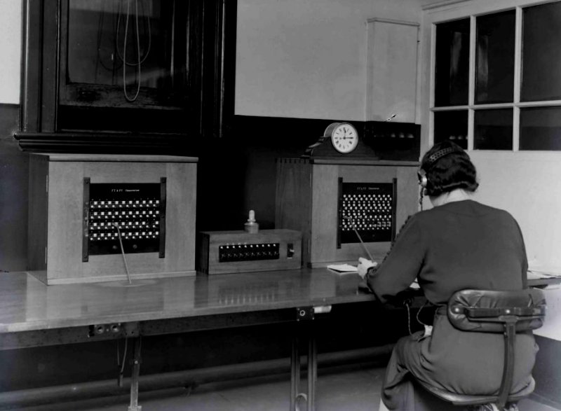
Fig. 3 - TELEPHONE-TELEGRAPH POSITION Distribution Positions
Fig. 4 - DISTRIBUTION POSITION The facilities provided by the distribution positions are:-
The circuit is shown in Fig. 5, and a brief description of its operation follows. When the calling plug of a telephone-telegram position cord circuit is inserted into the outgoing jack of a direct telephone-telegram circuit the line circuit K relay operates. Contact K3 lights the circuit busy lamp associated with this circuit on the distribution panels. Cord circuit relays HC, HCC, HD and HDD operate. Contact HDD3 operates relay I, which at contact I2 prepares a circuit for the lighting of the circuit lamp on the position keyboard. Contacts HCC3 and HDD2 prepare a circuit for the lighting of the position lamp. Assuming that a message came to hand for transmission over the above circuit, the operator at the distribution position, observing from the glowing of the circuit busy lamp that the circuit was already engaged, would operate the circuit key associated with the lamp. The operation of this key causes relays A and D to operate to earth via the uniselector wiper W1. Contact A1 provides a holding circuit for these two relays. Contact D2 removes a short-circuit from across the 3,000ohm resistance in the sleeve circuit of the engaged line. This reduces the current flowing in the sleeve circuit and results in relay HDD releasing. Contact HDD2 extends battery via relay HA, metal rectifier, "close down" and "reserve" keys and wiper W3 of the uniselector to earth, thus causing relay HA to operate. Contact HA3 lights the required position lamp on the distribution panel and also operates relay L. Contact L1 operates relay F, which, at F1, lights the circuit hold lamp and operates relay G. Contact G1 locks the G relay, thus maintaining the circuit hold lamp alight. The operator at the distribution panel notes the required position number and marks it on the message. The message is then placed on a conveyor serving the suite containing this position. When it is received at the drop point serving this suite a circulation officer delivers the message by hand to the position concerned, and at the same time operates the reset key on the position keyboard. This breaks the locking circuit of relay G which releases and thereby extinguishes the circuit hold lamp. The position lamp darkens immediately the operator at the distribution panel releases the circuit key, but the circuit busy lamp remains glowing as long as the circuit is engaged. The circuit operation, when the incoming side of a direct telephone-telegram circuit is concerned, is similar to the above. During busy periods it is necessary to staff both distribution positions, and the operators staffing each position must have access to every direct telephonetelegram circuit. The whole of the circuits must therefore appear on each distribution panel. It was not possible to have a simple multiple of the lamps and keys, because under such conditions a key operated on either panel would light the position lamp on both panels. This would cause serious inconvenience when both operators were pressing different circuit keys simultaneously as two position lamps would glow on each panel, and neither operator would be able to determine which of these lamps was associated with her particular circuit key. The difficulty was overcome by arranging for the whole of the 96 telephone-telegram positions to be connected to each panel alternately. A uniselector stepping under the control of earth pulses supplied by a special cam on the ringing machine is used to effect the switching of the positions, which are connected to each panel in turn for approximately four seconds. Under this scheme, if a key is operated on one panel when the positions are connected to the other it is only necessary to hold the key for a very short period, at the end of which time the positions will be connected to the panel concerned. This period of waiting, when it occurs under actual working conditions, is barely perceptible. A key is provided so that the uniselector . may be switched in or out of circuit as required. Another key is provided to bring in a spare uniselector should a fault develop on the working switch. Distribution Speaker Circuit When an operator has a message for a direct telephone-telegram circuit which tests engaged, she plugs into the speaker circuit jack. This causes the calling lamp to glow at the distribution position and draws attention to the fact that an enquiry is about to be made. The operator then quotes the code of the engaged circuit, and, on being informed of the number of the position engaging this particular circuit, marks the message accordingly and arranges for it to be delivered to the required position. The action of the distribution operator when ascertaining at which position the circuit is engaged results in the glowing of the circuit hold lamp at the engaging position. Thus the operator at this position is warned that another message is being circulated to her for transmission over the circuit she is engaging.
FIG. 5 - DISTRIBUTION POSITION CIRCUIT Telephone-Telegram De-concentration Positions In order to connect any one of the selected circuits to a de-concentration position it is only necessary to insert the plug of that position into the required circuit jack on the de-concentration switchboard. A listening circuit is provided so that the officer extending the circuits may, by listening on the line, ensure that a call is not in progress before the circuit is extended. It is possible that a circuit may be left through to a de-concentration position when the latter is unstaffed. In this case the line lamp at the position would glow on receipt of a call but, being on the keyboard, would probably escape notice for some considerable time. As a guard against this a lamp has been provided on each circuit in the switchboard jack field and is switched in whenever the circuit is extended. Should the circuit be left extended after the operator has vacated the position any further calls will light this lamp, which will readily be seen by staff who are always in the vicinity of the switchboard. A telephone circuit is provided on the switchboard so that the controlling office may give assistance when required. When a direct telephone-telegram circuit is extended to a de-concentration position its appropriate circuit keys on the distribution panels are designated with the number of the particular position to which the circuit is connected, thus indicating to which point messages for this particular circuit should be circulated.
Fig. 6 - DE-CONCENTRATION POSITIONS Phonogram Cord Circuit The answering side of the circuit is simply the standard C.B. arrangement. The calling side is arranged to discriminate between junctions to automatic exchanges and junctions to manual exchanges. Briefly, the circuit operation is as follows :- When the calling plug is inserted into a jack outgoing to an automatic exchange it meets a high resistance earth on the sleeve of the jack. This results in the cord circuit relays HC and HCC operating, but not HD or HDD. Contact HCC3 disconnects the engaged test circuit while HCC2 lights the calling supervisory lamp. Loop dialling conditions now exist on the calling cord, and the operator completes the call in the normal manner. When the called party answers the reversal of the battery and earth at the automatic exchange causes the polarised relay DC to operate. Contact DCl extinguishes the calling supervisory lamp, thus giving standard supervisory conditions. If the calling plug is inserted into a jack outgoing to a manual exchange it meets a low resistance earth on the sleeve of the jack. This results in relays HC, HCC, HD and HDD operating. The first two relays perform much the same function as on a call to an automatic exchange, while contacts HDD l and 2 substitute CB conditions for loop dialling conditions on the calling cord.
Fig. 7 - DISTRIBUTION POSITION CIRCUIT Position Lamps and Traffic Indicators Traffic indicators consisting of milliamperemeters fitted with suitable shunts, and calibrated to indicate numbers of positions, are mounted on the supervisors' desks. One "Positions Staffed" and one "Positions Engaged" indicator are common to a certain number of phonogram and telephone-telegram positions. The indicators serving the phonogram suites can be seen in position on a supervisor's desk, on the right in Fig. 1. By comparing the readings of the two indicators for each group of positions the supervisors are able to see at a glance whether the staffing arrangements require attention. The circuit arrangement, which is quite simple, is shown in Fig. 7. Free Line Signalling Facilities Listening Facilities As the listening-in position is situated some considerable distance away from the suites of positions it was necessary to take precautions against crosstalk between operating positions arising from the long length of cable carrying the listening-in leads. It is for this reason that a relay has been provided in the circuit at each position. The listening-in taps are thus disconnected from the operator's circuit until listening-in is actually in progress on the circuit. A transformer has been provided in the common listening-in circuit to ensure that the action of listening-in does not introduce any appreciable loss on the circuit under observation. Any position may be extended from the listening-in panel to the supervisors' desks by means of doubleended cords and extension jacks. The arrangements are such that even when a position is extended in the above manner the listening-in taps are not connected to the operator's circuit unless the supervisor is actually listening on the circuit. Observation Facilities There are two observation panels equipped to accommodate thirty line circuits. The line jack and line lamp fields of the panels are connected in multiple. Immediately above each strip of line jacks is a designation strip to carry labels bearing the appropriate circuit code for each jack. The labels consist of "Pegs No. 15, White," suitably engraved, and are changed by the traffic staff to agree with the circuits connected to the panels at any time. The red and green lamps indicating exchange and phonograph operator conditions respectively are fitted at the bottom of the panel. When a line is connected up for observation, but is not actually being observed, the circuit arrangements are such that the tapping equipment is short circuited. This ensures that there is no loss on the circuit unless it is actually under observation.
Fig. 8 - PHONOGRAM OBSERVATION PANELS Earthing Scheme Photogram Concentration Facilities
Ancillary Switching Cabinets The operation of the keys cuts in or out the different ancillaries as required. The keys are also used for closing down or opening up suites as the traffic load vanes. Additional Pictures
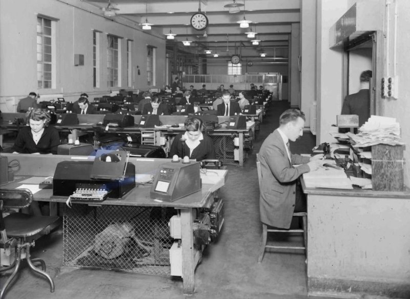
Printergram - Old Switchboard Suite (Picture dated 1954)
Printergram - New Switchboard Suite (Picture dated 1954)
|
||||||||
Last revised: February 21, 2026FM2 | ||||||||