Tetney Beam Radio Station | ||||||||
| All the pictures below were taken in 1928 when
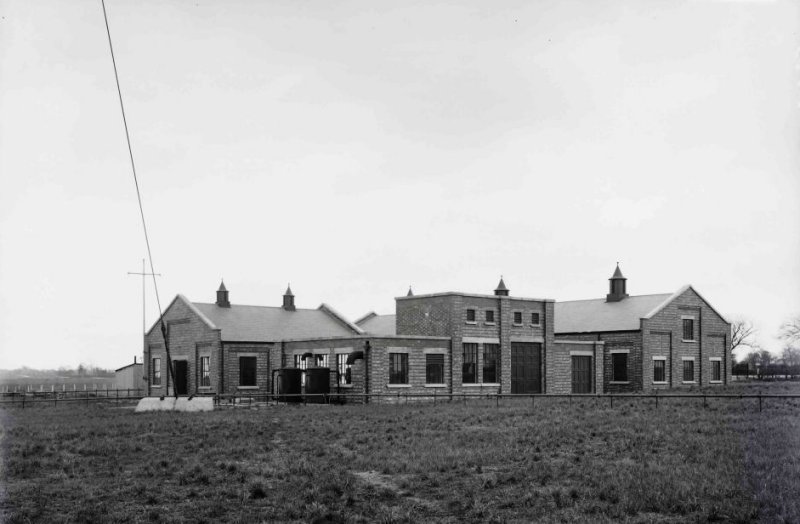
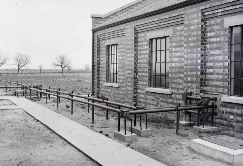
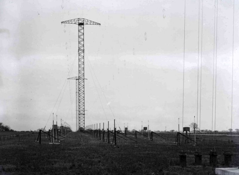
the station was brought into service. Tetney, Grimsby (Lincs) was the transmission station for India and Australia. The Indian aerial was nearly half a mile (800m) long, and consisted of a row of five 285 feet (84m) high lattice masts, erected in a line at 640 feet (200m) intervals, while the Australian aerial was carried on three 275 feet (84m) high masts. The aerials themselves looked like curtains of vertical wires hanging from the triatic bearers between the cross-arms at the tops of the masts. Each wire was attached at the lower end to a balance weight arm which kept the wire in tension. The lower end of each pair of aerial wires was connected to a special box and these in turn were connected by a system of copper pipes or feeder tubes to the particular transmitter. Tetney Beam was the transmitter station and Winthorpe Beam was the receiver station. Note that all the high voltage equipment, within the building, is fenced off and locked up. The voltages on this equipment is highly dangerous and would be isolated before worked on. How do you send a Telegram to Australia The form was marked "Via Imperial" and telegraphed to the Central Telegraph Office (CTO) in London, probably by Morse. At the CTO the message was changed into dots and dashes and punched onto a paper tape. This tape was then fed into a transmitting machine which usually operated at 150 words per minute and the the signals were sent along land lines to Tetney. These lines were laid alongside the railway from London to Holton-le-Clay Station and then to the Beam Station. At the Beam Station they passed through a valve transmitter to the aerial and then transmitted to Australia. The aerial is in a fixed location aimed directly at Australia. The signal navigates the earths atmosphere and is collected by another set of aerials and a receiver located in Australia. The signals received are then sent by land line to the telegraph office where they are printed, in words and figures, on to a tape which would be pasted on a telegram form and then delivered to the recipient.
Site picture
Station Buildings
Station buildings
Feeder system leaving building
Balance weight and feeder system for Australian aerial
Aerial coupling box showing auto transformers
Balance weight for aerial wire
Indian and Australian aerials
Australian aerial
Indian aerial
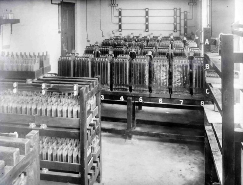
Battery room
Main power switchboard
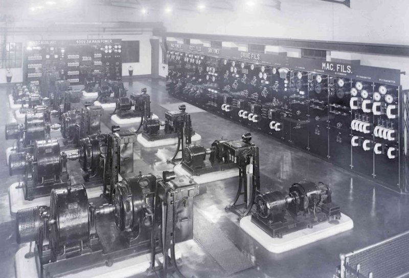
Machine room
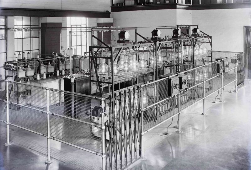
Rectifiers
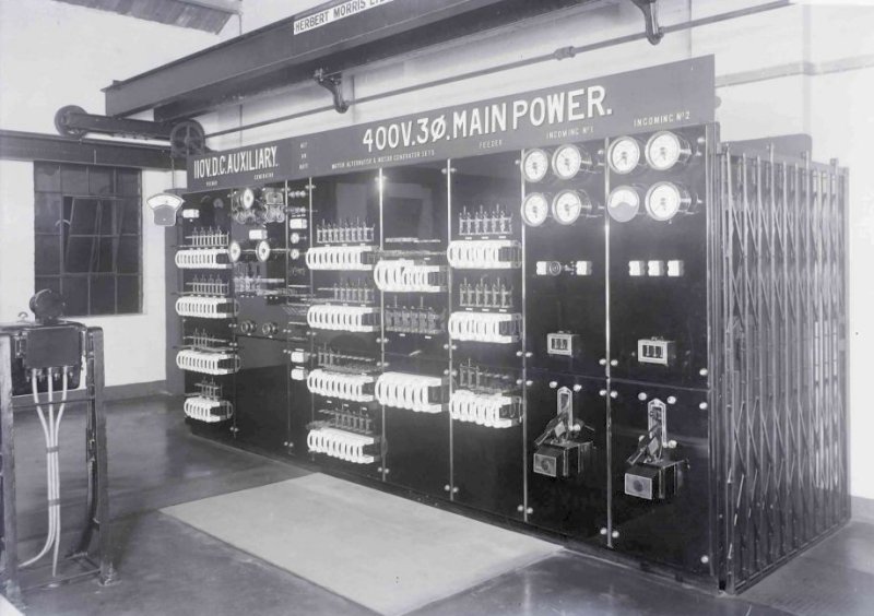
Main power and auxiliary power switchboard
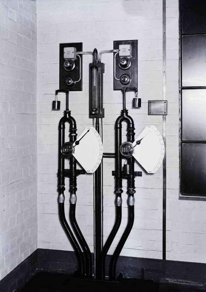
Flow meters for paraffin used in valve cooling
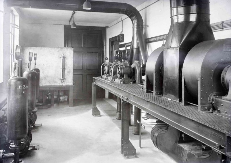
Blowers for absorber resistances and valves. Paraffin tank for valve coolant
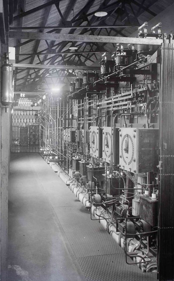
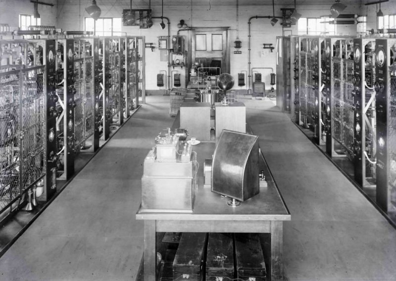
Transmitter room
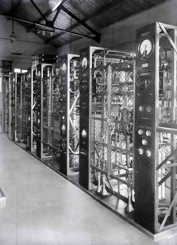
Australian transmitter
Indian Transmitter
|
||||||||
Last revised: February 21, 2026FM2 | ||||||||