ERICSSON
BULLETIN
No. 10 ERICSSON
BULLETIN
No. 10PAGE No. 33 | |||||||
|
P.A.X. Equipments at Broadcasting House P.A.X. installation at Broadcasting House has already been described in Bulletin No. 3. The ultimate capacity of the system originally
installed was 400 lines. However, after the exchange had been in commission for about three years the
B.B.C. had so extended their premises and personnel that this ultimate was considered quite inadequate; furthermore, the room housing the P.A.X. equipment would only accommodate an equipment for 400 lines. In view of these facts, it was decided to replace the existing installation by one giving an ultimate capacity of 1 ,000, and to utilize the power equipment and, as far as possible, the jacked-in equipment on the new installation; the whole of this equipment to be removed from the seventh floor to the lower ground floor.
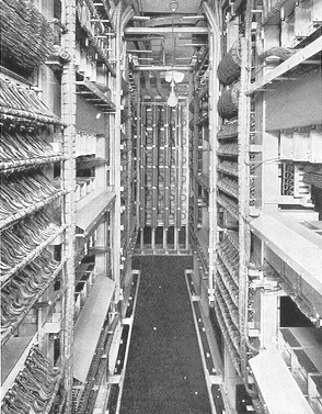
One illustration shows a front view of two units and a partial view of the combined main and intermediate distribution frame ; the other illustration shows the wiring side of the units, with the combined main and intermediate distribution frame in the background. A unit comprises all the necessary equipment, with associated alarms, for serving 100 lines. It consists of two panels, the right-hand one containing the line relays and line finders, and the left-hand one the ' jacked-in ' equipment
comprising group selectors, final selectors, assigner relay sets and main alarm relay set. The line finders are
50-outlet uniselectors, so that it is necessary to have two groups each consisting of seven finders, to serve the 100 lines. Group selectors of the two-motion,
100-outlet type, are directly connected to the line finders. They are seen in position on the upper two shelves 0f the left-hand panel of the unit. The group selector banks are fully wired to connection strips at the rear of the shelves and from there cabled to the intermediate distribution frame for grading and
cross connecting to final selectors. A group of eleven final selectors, also of the
two motion, 100-outlet type, serves the particular hundred lines associated with the unit. The banks are wired to connection strips at the rear of the shelves and from there cabled to the intermediate distribution frame.
It is interesting to note here that the eleven final selectors with access to the hundred subscribers on the unit, will carry, without undue loss, all the traffic originated by fourteen finders and group selectors, split into two groups, each with access to fifty subscribers. From the standard traffic curves, with a grade of service of one lost call in two hundred, a group of seven finder switches will carry 2.2 traffic units, whilst a group of eleven selector switches will carry 4.6 traffic units. Thus the total traffic originated by two groups of seven finders is 4.4 traffic units and is handled satisfactorily by a group of eleven final selectors. It will be noted from the illustrations that the jacked-in equipment is accommodated on channel type shelves, and that alarm fuse panels are fitted at the ends of the shelves to protect the equipment and to guard against fire risks. Twin contacts are fitted on all relays to minimize trouble that may be caused by dust. A grading chart is fitted on each unit showing the grading and cross connecting between the group selector level, associated with the particular unit, and its final selectors. It will be realized that there are only ten outlets on each group selector level, and that it is necessary to extend the group selector multiples from the various racks to the intermediate distribution frame, to provide a centralized field for grading and cross-connecting to the eleven final selectors associated with each level. A small portable tester allows a quick routine of all the switching and line equipment to be made. The following special operating features are incorporated on this installation:- |
|||||||
Last revised: October 14, 2019FM3 |