LONDON FIRE CALLOUT SYSTEM
| |||||||
|
The London Fire Brigade Alarm System London Fire Brigade Headquarters have recently been rebuilt and modern equipment installed. The conversion of all stations in the area to the "Gamewell" system, which has been adopted, is proceeding rapidly and the author gives details of the system and of the equipment. Introduction In the "Brown" system each street post is connected by a direct pair to a common battery at the station via a flap indicator. When a point is "pulled" the line circuit is closed, causing the flap of the indicator to fall, exposing its designation and a line jack, and actuating the station alarm bell. The contact is kept closed by an electromagnet within the head, until released by the watch-room attendant plugging into the line jack and disconnecting the line current. Each street point is also equipped with a buzzer which produces a distinctive signal when the point is pulled enabling the attendant to distinguish between genuine and false calls. In 1913 as the result of an unfortunate fatality the Brigade intimated that they had ceased to place reliance in the buzzer signal and from that date they have turned out for any and every indication what so ever. In 1900 there were 675 posts. They had increased to 1,300 in 1928 and 1,732 in 1936. The number of calls received in 1936 was 9,297. Of these, 5,875 were genuine and 3,422 false. The false calls were divided between 1,304 malicious calls, and 2,118 calls due to electrical defects and other causes. Of the latter figure approximately 1,000 were attributed to electrical faults. It was with a view to reducing the number of abortive turnouts and the annual costs to the Brigade in rentals that in 1928 the Council approached the Post Office to aid them in providing their own system and the Post Office readily agreed to place its experience at the disposal of the Council. Following protracted cost studies the Council decided to accept the Gamewell, code signalling, closed circuit, system which was considered to be the most satisfactory, and an experimental system of 26 street boxes arranged on two loops, was provided and installed in 1931 by Messrs. Standard Telephones & Cables, Ltd., at the late Headquarters station in Southwark. The Post Office conducted the negotiations and the placing of the contract, supervised the installation and the acceptance of the equipment, and recovered the cost, which included a nominal percentage service charge, from the Council under a repayment order. The line wires were of course rented from the Post Office which also undertook the maintenance of the equipment on rental terms. The system functioned satisfactorily and in 1936 the Council decided to proceed with the conversion programme commencing with the new Headquarters Station at Lambeth, to be followed by the "B" District. They expressed a wish, however, for certain later developments which were covered by patents associated with the apparatus manufactured by Messrs. Automatic Telephone & Electric Co., Ltd., to be incorporated in the street boxes. The contractors were approached and by agreement with the Council it was decided to accept street boxes of Messrs. Automatic Telephone & Electric Co.'s design and station equipment designed by Messrs. Standard Telephones & Cables. This has resulted in a division of the work between the two contractors. Work has been completed in the "B" District and the equipment was brought into use in November. There are ten stations including Clerkenwell, which is the superintendent station, and 299 street boxes. Messrs. Standard Telephones & Cables are installing the equipment at Whitefriars, Cannon Street, Redcross Street, Soho and Holloway, and Messrs. Automatic Telephones and Electric Co. have Clerkenwell, Euston, Islington, Camden Town and Kentish Town in hand. Instructions have also been received to proceed with the installations for Battersea and Shadwell new fire stations. Organisation of the London Fire Brigade There are 52 outstations and each has a direct telephone line to its superintendent station, each of which has in turn direct communication with the control room at headquarters, Lambeth. Each superintendent station has a direct line numbered 2222 to every telephone exchange in its district. Outstations have no direct exchange line, so that fire calls originated by the public over the telephone exchange network must necessarily be advised to the superintendent station. The alarm is then transmitted to the outstation concerned from the superintendent station by a fire signal over the direct telephone line, which rings the station alarm bells. While the firemen are manning the appliances ready to depart, the watchroom attendant ascertains the particulars of the fire and passes them to the station officer who rides on the first appliance to leave. An indicator at the superintendent station associated with the fire signal key is operated and remains in view until it is restored manually upon receipt of the advice from the outstation that the appliance has returned. If a call is received at an outstation from one of its street points the watchroom attendant transmits a fire signal to the superintendent station, which rings a local alarm bell only, and passes over details of the call. The indicator signifying "appliance out" is again operated and remains so until the appliance returns. The superintendent thus knows at any time the disposition of the fire fighting appliances in his area. The Brigade is organised so that as some stations are deprived of their apparatus in response to calls others are re-distributed to cover those stations. Particulars of all fires and the appliances attending them are notified to headquarters where a mobilisation map is marked to show the seat of the fires and the appliances attending. Fires which are beyond the capacity of an outstation to deal with become district calls upon which the district appliances are concentrated. If these cannot gain control over the conflagration a brigade call is circulated and appliances are drawn from the stations throughout the London area under the direction of the Mobilisation Officer at headquarters. This may mean as many as 60 pumps, escapes, etc., being employed. The remaining appliances are re-distributed over the area. The present equipment of the Brigade includes 68 pumps, 55 dual purpose appliances (escape and pumps), 35 escape vans and turntable ladders, 26 other appliances and 3 river floats. There are 31,311 fire hydrants and 52 miles of hose. The personnel comprises 1,980 uniform staff and 163 administrative, technical and other ranks. THE 'GAMEWELL' SYSTEM
The fundamental principles of the system are as follows :- 1. It is a closed circuit system. The diagram shows the electrical circuit in its simplest form. 2. The street fire alarm boxes are arranged in groups. The boxes forming a group, maximum 20, are connected in series by a single wire which passes progressively from one box to the next. 3. A small current of 50 milliamps is maintained around the loop by a battery at the fire station. The maximum permissible voltage of the battery is 50 volts. 4. Each box contains a powerful clockwork mechanism which is employed to drive a code wheel which transmits signals to the fire station. 5. The various electromagnets in the recording equipment at the station are employed to release the energy of coiled springs. 6. Each box bears a code number of two, three, or four digits. The highest digit is 6. 7. Normally, the mechanism of each box is short- circuited by contacts held closed within the box. 8. When a box is "pulled" it commences to send its code after a short test interval. Impulse contacts in series with the line are intermittently made and broken in accordance with the code number of the box. A box coded 214 would transmit two impulses, followed by one and then by four. Between digits the circuit is disconnected. 9. The code number is sent three times, whereupon the mechanism stops and the short-circuit is restored. The signals are transmitted at a speed of 3 impulses per second. 10. Suitable apparatus is located at the fire station which gives visible and audible indication of the call. 11. A disconnection on the line due to a fault is recorded on the station apparatus and a "patching" switch is operated automatically, which earths the station battery and connects both ends of the fire loop bunched, to the recording apparatus. The system resorts temporarily to earth working. 12. The use of code signalling prevents a fault from being mistaken for a genuine call. 13. Calls can be received without loss of impulses under anyone of the following fault conditions:-
14. Calls incoming from the Gamewell loops can be automatically repeated to a central or superintendent station over a repeat loop. 15. Two types of alarm boxes are used:-
The plain Sector box is employed on small installations where the possibility is remote of two boxes on the same loop being pulled simultaneously. On large installations this condition is more likely to arise, and from a consideration of the diagram above, it will be seen that if a second box is pulled while one is already transmitting, they world interrupt each other's signals and the record at the station would be unintelligible. To prevent this, the succession box was introduced. With this type more than one box can be pulled simultaneously on the same loop without interference. The succession feature causes each box to await its turn to transmit its code, the order of succession being controlled strictly in accordance with the chronological order in which the boxes were pulled. When a box is once "pulled" further operation of the handle cannot affect the working of the mechanism, until it has transmitted its code and reset itself. Succession Alarm Box The inner and outer boxes are insulated electrically from each other. When a box has been operated for a fire call, the projection R prevents the other door,
when opened by the visiting fireman, from being closed until the spring of the code
mechanism is fully wound. In conjunction with the door shunt contacts G, it also
short-circuits the testing equipment when the outer door is closed. Projection S ensures
that the act of closing the outer door will also close the inner door if this should be
open.
Fig. 3 - Interior of the succession alarm box Electrical Connections
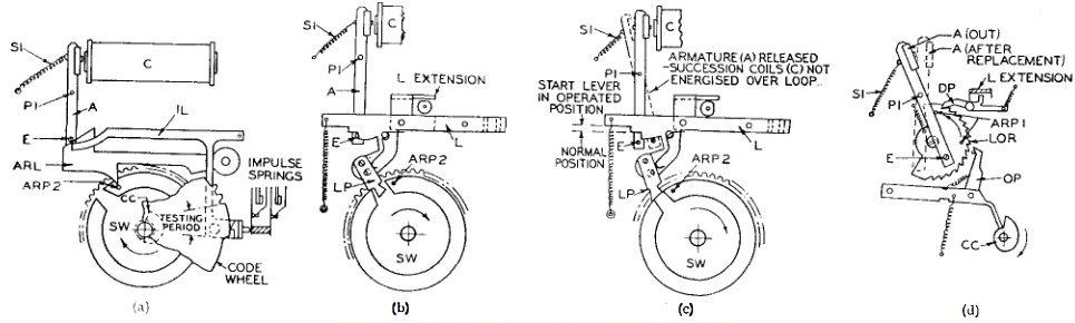
Fig. 4 - Connections of the succession alarm box Had either line A or B been broken due to a fault, when the box was pulled, the circuit would have previously been switched at the fire station for earth working i.e., with an earthed battery to both lines in parallel. The imputing circuit would then have been over the good line through one line succession coil, the impulse springs, earth succession coil, earth spring, rectifier, to earth. With a line current of 50 milliamps, the rectifier offers a resistance of approximately 60 ohms. Its function is to prevent a box in operation being short-circuited if the boxes on either side are pulled at the same time. Testing Facilities Telephone Calls The station is able to call the attention of the attending firemen by operating a howler key. The howl being received at the box in the hand microphone receiver. Signalling Key Silent Test When the alarm mechanism is set in motion, the impulse springs alternately disconnect and reconnect the succession coils (B) with the tap bell (N) in series across the 250ohm coil. The code of the box is tapped out on the bell but the continuity of the loop circuit is undisturbed. Arrester and Test Block Mechanism Operation, Normal Call For the space of approximately 3 seconds the signal lever IL passes over the long test tooth (Fig. 5 (a)), testing the line and the impulse springs are kept closed. If the line current is maintained, i.e. no other box imputing, the armature will remain attracted and the signal lever IL will follow the projection of the code wheel, transmitting the code. The normal condition of the line is, during imputing, a disconnection and the signals consist of a series of "makes" until the signal lever rests again upon the long test tooth, whereupon continuity is re-established. The armature is retained in position while the line is disconnected at the imputing springs by the pin E, resting against the end of the signal lever IL (Fig. 5 (a)). When the code wheel has completed one revolution, the pawl LP drops into the gap in the stop wheel SW and stops the mechanism (Fig. 5 (b)) Call with line already in use The line current is insufficient to attract the armature, once released, against the retractive force of the spring SI. At the end of each revolution however, pin ARP2 on the stop wheel (Fig. 5 (a)), engages with the cam face of lever ARL, which thrusts against pin E and presents the armature to the coils. At the moment the armature is presented to the coils the test tooth reaches the impulse lever IL. A further test of the line is made. The armature is either retained by the line current which has been restored, and the box then sends its code as in the normal call, or, it is released again by a disconnection of the line, and the code wheel runs for a further idle revolution. To prevent the box from running down should a break occur in the line, the mechanism is arranged to stop after 8 revolutions of the code wheel. A full run for one winding is 18 revolutions. A cam CC (Fig. 5 (d)), mounted on the same shaft as the code wheel, actuates the pawl lever OP which advances the ratchet wheel LOR in an anti-clockwise direction, one tooth per revolution of the code wheel. The ratchet wheel is locked at each stop by the pawl DP. As the code wheel approaches its normal position at the eighth revolution, the pin ARPI engages with the armature A, advances it to the coils and holds it there. Pin E is carried clear of the start lever allowing pawl LP to drop into the slot in the stop wheel and the mechanism stops.
Fig. 5 - Details of the code mechanism STATION EQUIPMENT At stations where there is an A.C. supply each Gamewell loop is equipped with a single 50 volt, 10Ah battery which is floated across a metal rectifier. A single 24 volt, 30Ah battery, floated, is provided for operating telephones, relays, bells, displays, alarms and miscellaneous station apparatus. At stations with a D.C. supply the batteries are provided in duplicate and worked on a charge-discharge basis, the batteries off-load being charged direct from the mains through rheostats. There is in addition, at the superintendent station, a common 50 volt, 60Ah battery (or batteries) which serves all the incoming repeat loops. Fig. 6 shows shows the station equipment installed at Headquarters, Lambeth. The combined auxiliary and repeat panel is in the centre, and the box loop panels and register cabinets are on either side. Above the panels is the illuminated display, which, in conjunction with a common alarm bell and the panel pilots, gives a positive indication of circuit functions and fault conditions. The displays are fire, fuse, enquiry, short-circuit, telephone, circuit broken, earth, mains failure, fire telephone. The two lamps surmounting the ensemble are emergency lighting.
Fig. 6 - Station equipment at Lambeth Box Loop Panel The five lamps which are coloured red, opal, green, green and red are the panel pilots, and are labelled, fire, fuse, short-circuit, earth and circuit broken respectively. The eight keys are test keys for use in ,conjunction with the meters, testing the lines and ,cancelling the displays. Within the glazed cabinet is the punch register and take-up reel which are both spring driven. The latter maintains the tape in tension. Fig. 7 shows a single circuit register with a typical tape record of a call. Within the body of the cabinet are located the battery charging equipment and circuit relays, fuses, etc. The loud sounding gong connected in series with the punch register is located in the station appliance room. A 6" dome of bell-metal, covers the spring driven mechanism. When the loop current is interrupted an electromagnet releases the hammer which is flung by the spring into violent contact with the dome, and registers one stroke. The electromagnet is re-energised when the current is restored, and re-engages the hammer which remains at rest until released by a further interruption in the line current.
Fig. 7 - Single circuit register Station Auxiliary and Repeat Panel The two sets of four keys are for cancelling the various displays in the above panel, measuring battery voltages and controlling emergency lighting. The battery of toggle switches between the meters operates several special displays about the building which indicate to the crews the appliances to be turned out, and so save the energy of those not required. They also keep the senior brigade officers in touch with the movement of the headquarters appliances. The centre knob is the charging rheostat. The first row of keys on the cabinet controls the house bells which summon the fire fighting personnel. Provision is made for ringing the bells-collectively or individually-automatically on an incoming fire call or signal from a superintendent station, or manually, as required. The lower keys are the telephone speaking and ringing keys with line lamps above, wired on the cordless board principle. The upper lamp of each of the four lines equipped with two lamps is the fire flash. These lamps are red, and intermittently flash when a fire signal is received. The circuits are connected to Southwark, which is the superintendent station controlling headquarters - Manchester Square, Clapham and the Control Room in the headquarters' building which all have the authority to turn out the appliances. The remaining four single keys cancel the display associated with enquiry bells at the three entrances to the building and the public fire pull let into the front wall. A hand micro-telephone and a draw leaf writing shelf complete the cabinet. The circuit relays and battery charging rectifiers are located within the body of the cabinet. Circuit Facilities Telephone Calls Broken Line
Fig. 8 - "Broken Line" circuit Line relay A releases (shown in the operate position) and operates F which actuates LB. LB lights the "broken circuit" display and pilot, and rings the alarm bell. One stroke is recorded on the gong and tape of the register. The tape runs for approximately 6 inches then stops. The contacts R on the register close momentarily immediately prior to this and operate RR and J which locks via JI and Al. Relay KK operates and locks via key RK. Lines 1 and 2 of the box loop are connected in parallel at KK5. Relay LB is held by KK3. The display and bell are cancelled by operating key CBK momentarily. Fire alarm calls can now be received over either leg of the loop and earth. Provision is made to prevent calls originated simultaneously on both legs from mutually interfering. When the line break is cleared the battery connections are restored to normal by operating, momentarily, key RK, which releases relays KK and LB and dims the pilot. Earth Detecting
Fig. 9 - Circuit for earth detection and box short-circuit Short-Circuited Boxes Repeat Loop
As its title suggests a 4-circuit register has four independent movements, side by side, which puncture a common tape. One register can therefore serve four separate repeat loops. Associated with the register and its take-up reel is a time and date stamp, shown on in the picture on the left. Contacts on the register operate the stamp at the conclusion of an incoming call, so that the tape record is timed and dated. The stamp is impulsed at half minute intervals from a master pendulum and will accurately register time and dates for 24 years (including leap years') without changing the character wheels.
Fig. 12 - Repeat panels at Clerkenwell Fig. 12 shows the repeat panels and cabinets for 10 loops as supplied to Clerkenwell. Each panel is equipped for 4 repeat loops, except the end panel on the right which carries 2 repeat loops and the repeat battery charging apparatus. The illuminated indicator above the panels displays the name of the station transmitting. The loop circulating current is regulated by the rheostats and recorded on the meters. Broken line faults cause the second pilot to glow and a display of "Broken Circuit" appears on the fault indicator above the end panel on the right. The keys on each panel are for testing and connecting the displays. The 4-circuit registers with take-up reels are shown behind the glazed drops of the cabinets. Telephone calls incoming and outgoing are con- trolled with other circuits on a two position lamp signalling switchboard specially designed, built and installed by the Post Office for the Brigade inter-communicating system. Conclusion The writer acknowledges, with thanks, the information supplied by Major C. C. B. Morris, M.I. Mech.E., Chief Officer of the Brigade, Messrs. Standard Telephones and Cables, Ltd., and Messrs. Automatic Telephone and Electric Co. Ltd.
|
|||||||
Last revised: December 30, 2023FM |

 This box is the one approved for installation in the London County
Council Fire Brigade area and incorporates features which were developed by the
Post Office. Fig. 2 shows the exterior view of the box mounted on it's
pedestal, the interior being shown in Fig. 4. The
inner box contains the code signalling Telephone Calls. The telephone is provided to
mechanism and the testing equipment. The hand micro-telephone and the trip lever
mechanism T which is actuated by the pull handle, are mounted behind the outer door. The Gamewell mechanism is further protected by being enclosed in a glazed
compartment. Below the Gamewell mechanism is the test panel.
This box is the one approved for installation in the London County
Council Fire Brigade area and incorporates features which were developed by the
Post Office. Fig. 2 shows the exterior view of the box mounted on it's
pedestal, the interior being shown in Fig. 4. The
inner box contains the code signalling Telephone Calls. The telephone is provided to
mechanism and the testing equipment. The hand micro-telephone and the trip lever
mechanism T which is actuated by the pull handle, are mounted behind the outer door. The Gamewell mechanism is further protected by being enclosed in a glazed
compartment. Below the Gamewell mechanism is the test panel.