|
GEC MAGNETO TELEPHONE SWITCHBOARDS
WALL PATTERN
Catalogue No. MS3130 series
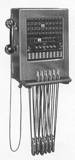 Switchboards with ten, twenty or thirty extensions
and three, five or six cord circuits make up this series. Switchboards with ten, twenty or thirty extensions
and three, five or six cord circuits make up this series.
Connexions are made by calling and answering cords through line jacks mounted at the bottom of the panel. Any pair of lines can be connected by any pair of cords. Between the jacks and the indicators are the alarm key, the combined RING/SPEAK keys, each associated with one cord circuit, and the common RING BACK key which connects the ringing generator to recall the extension that initiated a call. Both the extension line calling indicators and the cord circuit clearing indicators are of the hand-restored drop pattern.
The operator's telephone handset can be placed on
a hook at the side of the cabinet and is connected by a
plug.
The front and sides of the cabinet open out on hinges
to provide access to the wiring and apparatus.
FEATURES COMMON TO ALL MAGNETO SWITCHBOARDS
FACILITIES
Each of these switchboards enables its operator to set up calls between its extensions.
In addition, they can be supplied for connexion to any kind of public exchange.
Switchboards Catalogue Numbers MS4121-4 are wired for ten junction lines to a public exchange, which are equipped
if ordered. On the other switchboards a number of the lines provided can be converted, if ordered, to work as junction lines to a public exchange.
All boards are provided with a buzzer, which gives audible warning of incoming calls.
This alarm may be switched 'ON' or 'OFF' as desired.
CONSTRUCTION
The switchboards are housed in matt polished cabinets of seasoned hardwood which are of pleasing appearance and allow easy access to the wiring and apparatus they contain.
CAPACITY
All switchboards in the range are fully wired for the maximum number of lines stated, but can be supplied only partially equipped so that both immediate needs and future additions are catered for with maximum financial economy.
SIMULTANEOUS CONNEXIONS
The number of calls that may be passed through the switchboard simultaneously is determined by the number of cord circuits or connecting link circuits with which the switchboard is equipped.
This number is stated in the specification tables for every size in each range of switchboard.
POWER SUPPLY
The audible alarm and the operator's telephone instrument each operate from
a 3-volt battery of dry cells. Catalogue Numbers MS4130 series switchboards have two transmitter batteries for the operator's telephone circuit. Batteries are supplied if ordered.
RINGING SUPPLY
Ringing current may be drawn from the compact but powerful hand generator.
On certain of the switchboards provision is made for the connexion of ringing current from an external source, such as a local vibrator or ringing machine, or over power leads from the main exchange, to facilitate operation.
The hand generator then acts as a stand-by.
OPERATOR'S TELEPHONE
Whether a handset or headset is used, the circuit of the operator's telephone has great transmitting and receiving efficiency with full sidetone suppression.
CORDS
G.E.C. switchboard cords are of great durability. Their tinsel is tested to a life of
200,000 reciprocations without conductor fracture.
FINISH
The switchboards are supplied with a tropical finish to combat the effects of tropical climates.
TELEPHONE INSTRUMENTS
The instruments recommended as extensions with these switchboards are the G.E.C. Magneto Telephones, for table or wall mounting, described in Catalogue Leaflet
STL11.
SUPERVISION
Each line has an individual indicator which operates when the generator handle on the extension telephone
is turned. When the call is answered, the indicator is restored, either by the insertion of the plug or by hand. When, at the end of a conversation, the generator handle is again turned, a clearing signal is given by the operation either of the line indicator or of the cord circuit indicator. The audible
alarm, if switched 'ON,' sounds when any indicator operates,
LINE WIRES
Each extension may be connected to the exchange either by a single wire, with earth return, or by a twisted pair. For external lines, regular external line practice should be followed. For internal lines, any adequately insulated conductor may be used, and must be suitably protected if exposed to the risk of damp or of mechanical damage. If single-wire working is employed, each extension telephone should be effectively earthed at the 'B'-line terminal, and the 'R' ('B'-line) terminals In the switchboard should be commoned and also effectively earthed.
DISTRIBUTION, CABLING AND PROTECTION
The simplest method of connecting extension Instruments to the switchboard is to run the line wires of each instrument directly to the terminal strip within the switchboard. Economy in line wires, however, may often be effected by running a multi-core cable from the switchboard to a junction-box so situated that only a short length of individual connexion is then needed between each Instrument and the junction-box.
A distribution frame often simplifies the distribution scheme, particularly with a switchboard of large capacity. The wires from the switchboard, which are usually run in a multi-core cable, are terminated on one side of the distribution frame. The leads from the cable are then jumpered into numerical arrangement on the other side of the frame, to which the extension instruments are wired. The use of a distribution frame simplifies alterations to numbering, line testing and the connexion of additional lines. The frame can also be fitted with protection apparatus, providing protection against any high voltages and heavy currents that may accidentally be introduced from extraneous local sources.
In Installations without distribution frames, all lines run outside a building should be protected against lightning by protection apparatus, that is supplied when ordered.
| Catalogue Number |
Extension Lines |
Connecting Circuits |
Weight (kgs) |
Dimensions (cms) |
| MS3131 |
10 |
3 |
18.6 |
50.8 x 36.8 x 29.2 |
| MS3132 |
20 |
5 |
22.3 |
50.8 x 36.8 x 29.2 |
| MS3133 |
30 |
6 |
24.5 |
50.8 x 36.8 x 29.2 |
Taken from the GEC Catalogue No. MSL 5
|
 GEC
GEC