GOLDSTAR GSX408/816
INTRODUCTION
The GSX-408/816 Key Telephone System is
designed to meet the telecommunications needs of small to medium sized
businesses.
The Key Service Unit (KSU) is a wall
mountable unit that contains Key Service Board, Power Supply, Battery Backup
Unit, Real Time Clock Unit and pre-wired connectors for station and CO line
interfaces.
The GSX-408/816 is a flat pack system
equipped with 4 CO lines and 8 Stations. It
can be easily expanded to 8 CO lines and 16 stations with a modular PCB mounted
in the KSU.
Crane Telecommunications are the sole
importer of these systems into the UK. Goldstar
UK have nothing to do with them what so ever.
Installation manuals are scarce due the fact Crane Telecommunications
operated maintenance contracts on the systems and were reluctant to let the
owners carry out their own re-programming.
If the system is second-hand you will have trouble getting any support
for it at all.
Y2K Compliant.
TECHNOLOGY
The GSX-408/816 Key Telephone system is
a microprocessor controlled, solid state electronic switching system which
distributes communications in a non-blocking format. All control, switching interface circuitry is condensed onto
a single printed circuit board (PCB) located inside the key service unit.
Switching is accomplished through a
solid state crosspoint matrix that provides voice path connections for 4 (8)
central offices lines, 8 (16) key telephones and 8 intercom paths.
The CO interfaces are equipped with
transformer barriers for system classification as an FCC fully protected system.
Each CO circuit supports rotary or DTMF dialing under software control.
The DTMF tones and system supervisory tones are generated in each keyset.
The central microprocessor is a Z-80 and
controls the crosspoints and central office relays. It also controls
communications between slave microprocessor located in each GSX key telephone.
The 408/816 contains all system memory,
which is composed of 96K of Read Only Memory (ROM) and 16K of Random Access
Memory (RAM). The RAM is
sub-divided so that part is used for customer database.
A long life lithium battery protects the customer database memory.
The system general memory (ROM) is contained in a Program Module (PM)
that is interfaced to the KSU through a modular connecting arrangement.
This allows easy access for removal of system software when upgrading
software feature packages.
Each key telephone contains a
microprocessor and circuitry to monitor button activity and control lamp
conditions. A built-in speaker permits voice or tone calling to the station.
Every telephone has a flexible button field, which can be individually
programmed for 1 to 6 functions.
The key telephone sets are equipped with
9 fixed function buttons and either 12 or 24 flexible buttons which can be
programmed by individual users, 2 volume controls an intercom mode selection
switch and integrated speaker.
For emergency applications, a
stand-alone battery assembly may be connected to the battery-input terminals on
the KSU. This retains system power
in the event of commercial power failure.
SYSTEM CAPACITY
| 8 |
CO (Outside) Lines |
| 8 |
Intercom Channels |
| 16 |
Key Telephone Stations |
| 1 |
External Music Source Input |
| 1 |
External Paging port |
| 2 |
Loud
Bell Controls |
| 1 |
Alarm Input (NOT BURGLAR ALARMS!) |
| 1 |
24V DC Battery Connector |
| OPTIONAL |
|
| 1 |
RS232C Port for SMDR |
EQUIPMENT
DESCRIPTION
KEY SERVICE UNIT
 The KSU is a self-contained unit that contains the power supply, processor,
external connectors and circuits for 4 CO lines and 8 stations.
External connections use 50way Telco connectors.
A plug in module provides system-operating data in standard and advanced
feature package. The system is
provided with a real time clock to provide executive telephones with LCD, to
have time and date displayed, and a battery to keep clock accurate in case of
commercial power failure. This unit
also provides SMDR to track date and time.
The KSU is a self-contained unit that contains the power supply, processor,
external connectors and circuits for 4 CO lines and 8 stations.
External connections use 50way Telco connectors.
A plug in module provides system-operating data in standard and advanced
feature package. The system is
provided with a real time clock to provide executive telephones with LCD, to
have time and date displayed, and a battery to keep clock accurate in case of
commercial power failure. This unit
also provides SMDR to track date and time.
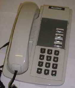
KEY TELEPHONE
The 4-button telephone comes with 4 fixed feature buttons. 1 volume control
and message waiting lamp.
The 8 button has the same size wit
4-button telephone but comes with 2 fixed feature buttons, 6 programmable
buttons, 1 volume control and message waiting lamp.
The 21-button telephone comes in 2
models, Enhanced and Executive. Both
models come with 9 fixed feature buttons, 12 programmable buttons, speakerphone,
2 volume controls, and intercom mode selection switch.
In addition, the Executive model comes with a 2-line, 48-character LCD
display.
The 33 button is similar to the
21-button but comes with 24 programmable buttons.
Is also available in enhanced and executive style.
 |
|
 |
| 4 Button
Key Telephone |
|
21
Button Key Telephone |
PHONE BOX
The unit is basically a wall-mounted unit that is used for door-opening
facilities. The system can handle a
maximum of 8 of these units.
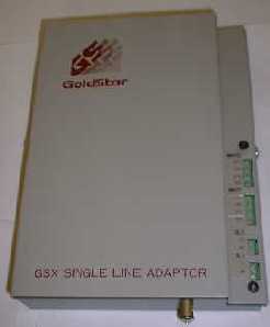 SINGLE LINE ADAPTOR
This unit (shown pictured to the right) is for converting connection that would be intended for a key
telephone and convert the signals so that a normal POTS telephone can attached
to the system i.e. modem, answer phone etc. etc.
DIMENSIONS AND WEIGHT
KEY SERVICE UNIT
Height 419mm
Width 298mm
Depth 76mm
Weight 8KG
KEY TELEPHONE
Height 222mm
Width 222mm
Depth 70mm
Weight 1.5KG
PHONE BOX
Height 44mm
Width 140mm
Depth 102mm
Weight 0.5KG
EXPANSION MODULE
Height 279mm
Width 140mm
Depth 25mm
Weight 0.8KG
NUMBERING PLAN
| 100-115 |
Station Numbers |
| 250-255 |
Call Park locations |
| 260-267 |
Hunt Group Pilot Numbers |
| 281
(ATND) |
WAKEUP Registration-effective until
cancel |
| 282
(ATND) |
WAKEUP Registration-one time only |
| 283
(ATND) |
WAKEUP Cancel |
| 284
(ATND) |
PASSWORD Erase |
| 285
(ATND) |
LCD Format-ddmmyy/mmddyy (toggle) |
| 286
(ATND) |
LCD Format-am-pm/24 hour (toggle) |
| 299
(ATND) |
Clock |
| 3 |
Camp On (Call Wait) |
WIRING CONNECTION
CO LINES
The CO Lines are connected to the RHS of the KSU on a 50 Way Telco
connector.
|
PAIR
|
CO Line
|
COLOURS
|
|
1
|
1
|
BLUE / WHITE
|
|
2
|
2
|
ORANGE/WHITE
|
|
3
|
3
|
GREEN/WHITE
|
|
4
|
4
|
BROWN/WHITE
|
|
5
|
5
|
GREY/WHITE
|
|
6
|
6
|
BLUE/RED
|
|
7
|
7
|
ORANGE/RED
|
|
8
|
8
|
GREEN/RED
|
|
PAIR
|
CO POWER FAIL
|
COLOURS
|
|
21
|
1
|
BLUE/PURPLE
|
|
22
|
2
|
ORANGE/PURPLE
|
|
23
|
3
|
GREEN/PURPLE
|
|
24
|
4
|
ORANGE/PURPLE
|
Pairs 21-24 provide CO lines 1-4 back
out of the system if there is a power failure.
They will not show current if the system is powered up.
STATION WIRING
Normally when the systems are installed for the first time, the supplier
will have connected the pairs to KRONE IDC strips.
Extension 100 will be on the first 2 pairs of the loom (Blue/White and
Orange/White). The rest of the extensions will follow on until Extension 107,
for extension 108 to 115 the loom cable will be the same as before but just plug
it into the connector on the KSU for that extension range.
For the wiring of cables to a PSTN socket for extension 100, it is like
so: -
| WHITE/BLUE |
- |
PSTN OUTLET PIN #4 |
| BLUE/WHITE |
- |
PSTN OUTLET PIN #3 |
| WHITE/ORANGE |
- |
PSTN OUTLET PIN #5 |
| ORANGE/WHITE |
- |
PSTN OUTLET PIN #2 |
You will need to have a lot creative
license to finally get all the rest of the stations wired up but it is fairly
easy if you follow the standard that is used for extension 100.
Do not use PSTN Master sockets as they
make the KSU/KEY Phone appear to be faulty when it isn't only use secondary
sockets.
If you wire the socket up incorrectly
you may get no response or possibly a full LCD screen test combined with
interference sounds emitted from the speaker, then all goes dead on the handset
MUSIC ON HOLD / EXTERNAL PAGING
The connections on the side of the KSU for these inputs and outputs are
fairly well UN-DOCUMENTED! On the
wiring loom for the extensions, pair 17 (ORANGE/YELLOW) are for connection of a
of music device e.g. CD-Player, Radio etc. etc.
Pair 18 is for connection to an external P.A system.
PROGRAMMING
To enter program mode dial *7764 from
station 100. When programming it
advisable to use an executive 21//33 key telephone. Programming can be achieved by using an enhanced but the LCD
gives on-screen guidance.
To enter the programming menus press the
recall button followed by the 2-digit program code.
Some menus appear twice but when they
are entered into, they actually adjust different parameters even though they
look the same.
PROGRAMMING CODES
This section provides all the
programming codes for the system. Some
codes have sub menus so be thorough.
|
Key
|
Use
|
|
Key
|
Use
|
|
|
1
|
System Hold Re-Call
|
|
21
|
|
|
|
2
|
Exclusive Hold Re-Call
|
|
22
|
Pulse Dialing Parameters
|
|
|
3
|
Transfer Re-Call
|
|
23
|
|
|
|
4
|
Preset Forward Timer
|
|
24
|
|
|
|
5
|
Pause Timer
|
|
25
|
ICM Box Timer ( Door Phone)
|
|
6
|
Call Park Timer
|
|
26
|
|
|
|
7
|
|
|
27
|
Background Music Channel
|
|
|
8
|
Message Waiting Tone Timer
|
28
|
Date & Time
|
|
|
9
|
Paging Time Out
|
|
29
|
Monitor Mode
|
|
|
10
|
CO Ring Detect
|
|
30
|
CO Line Attributes
|
|
|
11
|
Hold Preference
|
|
31
|
|
|
|
12
|
|
|
32
|
|
|
|
13
|
Ext Night Ring
|
|
33
|
Attendant Re-Call
|
|
|
14
|
|
|
34
|
|
|
|
15
|
Attendant Station Assignment
|
35
|
|
|
|
16
|
Loud Bell Assignment
|
|
36
|
|
|
|
17
|
PBX Dial Codes
|
|
37
|
|
|
|
18
|
Executive Secretary Pairings
|
38
|
|
|
|
19
|
Hunt Groups
|
|
39
|
Multi Line Conferencing
|
|
|
20
|
SMDR Parameters
|
|
40
|
Station Attributes
|
|
|
Key
|
Use
|
|
Key
|
Use
|
|
41
|
|
|
61
|
Initialize CO Lines
|
|
42
|
|
|
62
|
Initialize Stations
|
|
43
|
|
|
63
|
Initialize Exclusion Tables
|
|
44
|
|
|
64
|
Initialize System Speed Numbers
|
|
45
|
|
|
65
|
|
|
46
|
|
|
66
|
|
|
47
|
|
|
67
|
|
|
48
|
SMDR Timer
|
|
68
|
|
|
49
|
SMDR Long Distance Codes
|
|
69
|
|
|
50
|
Exception Tables
|
|
70
|
Print System Data
|
|
51
|
New Tel. No Plan
|
|
71
|
Print System Parameters
|
|
52
|
Station Attributes
|
|
72
|
Print CO Lines
|
|
53
|
|
|
73
|
Print Stations
|
|
54
|
|
|
74
|
Print EX Tables
|
|
55
|
|
|
75
|
Print System Speed No
|
|
56
|
CO Delay Timer
|
|
76
|
Print Least Cost Routing
|
|
57
|
|
|
77
|
Print New STD Tables
|
|
58
|
|
|
78
|
|
|
59
|
|
|
79
|
|
|
60
|
Initialize System Parameters
|
|
80
|
|
|
Key
|
Use
|
|
81
|
Least Cost Routing Enable
|
|
82
|
Inhibit BT Access
|
|
83
|
LCR Access Codes
|
|
84
|
LCR Authorization Codes
|
|
85
|
LCR Dial Tone Detect Timer
|
|
86
|
LCR Lookup Table
|
|
87
|
New Mercury STD Table
|
|
88
|
MCL Extension Billing
|
|
89
|
Disable 30 Sec
|
|
90
|
|
|
91
|
Paging Timeout
|
|
92
|
|
|
93
|
Monitor Mode
|
|
94
|
|
|
95
|
SMDR Long distance Codes
|
|
96
|
|
|
97
|
|
|
98
|
|
|
99
|
Disable 30 Sec
|
|
100
|
|
Wiring
Diagram showing all connector uses published to date
|
|
Extension
100 -107 Loom
|
|
|
|
|
Extension
108 -115 Loom
|
|
|
|
|
CO
Line Loom
|
|
|
|
|
|
|
|
|
|
|
|
|
|
|
|
|
Pair
|
Colour
|
PIN
|
Use
|
|
Pair
|
Colour
|
PIN
|
Use
|
|
Pair
|
Colour
|
Use
|
|
1
|
White/Blue
|
4
|
|
|
1
|
White/Blue
|
4
|
|
|
1
|
White/Blue
|
CO 1
|
|
1
|
Blue/White
|
3
|
Ext
|
|
1
|
Blue/White
|
3
|
Ext
|
|
1
|
Blue/White
|
|
|
2
|
White/Orange
|
5
|
100
|
|
2
|
White/Orange
|
5
|
108
|
|
2
|
White/Orange
|
CO 2
|
|
2
|
Orange/White
|
2
|
|
|
2
|
Orange/White
|
2
|
|
|
2
|
Orange/White
|
|
|
3
|
White/Green
|
4
|
|
|
3
|
White/Green
|
4
|
|
|
3
|
White/Green
|
CO 3
|
|
3
|
Green/White
|
3
|
Ext
|
|
3
|
Green/White
|
3
|
Ext
|
|
3
|
Green/White
|
|
|
4
|
White/Brown
|
5
|
101
|
|
4
|
White/Brown
|
5
|
109
|
|
4
|
White/Brown
|
CO 4
|
|
4
|
Brown/White
|
2
|
|
|
4
|
Brown/White
|
2
|
|
|
4
|
Brown/White
|
|
|
5
|
White/Grey
|
4
|
|
|
5
|
White/Grey
|
4
|
|
|
5
|
White/Grey
|
CO 5
|
|
5
|
Grey/White
|
3
|
Ext
|
|
5
|
Grey/White
|
3
|
Ext
|
|
5
|
Grey/White
|
|
|
6
|
Red/Blue
|
5
|
102
|
|
6
|
Red/Blue
|
5
|
110
|
|
6
|
Red/Blue
|
|
|
6
|
Blue/Red
|
2
|
|
|
6
|
Blue/Red
|
2
|
|
|
6
|
Blue/Red
|
CO6
|
|
7
|
Red/Orange
|
4
|
|
|
7
|
Red/Orange
|
4
|
|
|
7
|
Red/Orange
|
|
|
7
|
Orange/Red
|
3
|
Ext
|
|
7
|
Orange/Red
|
3
|
Ext
|
|
7
|
Orange/Red
|
|
|
8
|
Red/Green
|
5
|
103
|
|
8
|
Red/Green
|
5
|
111
|
|
8
|
Red/Green
|
CO 7
|
|
8
|
Green/Red
|
2
|
|
|
8
|
Green/Red
|
2
|
|
|
8
|
Green/Red
|
|
|
9
|
Red/Brown
|
4
|
|
|
9
|
Red/Brown
|
4
|
|
|
9
|
Red/Brown
|
CO 8
|
|
9
|
Brown/Red
|
3
|
Ext
|
|
9
|
Brown/Red
|
3
|
Ext
|
|
9
|
Brown/Red
|
|
|
10
|
Red/Grey
|
5
|
104
|
|
10
|
Red/Grey
|
5
|
112
|
|
10
|
Red/Grey
|
N/A
|
|
10
|
Grey/Red
|
2
|
|
|
10
|
Grey/Red
|
2
|
|
|
10
|
Grey/Red
|
N/A
|
|
11
|
Black/Blue
|
4
|
|
|
11
|
Black/Blue
|
4
|
|
|
11
|
Black/Blue
|
N/A
|
|
11
|
Blue/Black
|
3
|
Ext
|
|
11
|
Blue/Black
|
3
|
Ext
|
|
11
|
Blue/Black
|
N/A
|
|
12
|
Black/Orange
|
5
|
105
|
|
12
|
Black/Orange
|
5
|
113
|
|
12
|
Black/Orange
|
N/A
|
|
12
|
Orange/Black
|
2
|
|
|
12
|
Orange/Black
|
2
|
|
|
12
|
Orange/Black
|
N/A
|
|
13
|
Black/Green
|
4
|
|
|
13
|
Black/Green
|
4
|
|
|
13
|
Black/Green
|
N/A
|
|
13
|
Green/Black
|
3
|
Ext
|
|
13
|
Green/Black
|
3
|
Ext
|
|
13
|
Green/Black
|
N/A
|
|
14
|
Black/Brown
|
5
|
106
|
|
14
|
Black/Brown
|
5
|
114
|
|
14
|
Black/Brown
|
N/A
|
|
14
|
Brown/Black
|
2
|
|
|
14
|
Brown/Black
|
2
|
|
|
14
|
Brown/Black
|
N/A
|
|
15
|
Black/Grey
|
4
|
|
|
15
|
Black/Grey
|
4
|
|
|
15
|
Black/Grey
|
N/A
|
|
15
|
Grey/Black
|
3
|
Ext
|
|
15
|
Grey/Black
|
3
|
Ext
|
|
15
|
Grey/Black
|
N/A
|
|
16
|
Yellow/Blue
|
5
|
107
|
|
16
|
Yellow/Blue
|
5
|
115
|
|
16
|
Yellow/Blue
|
N/A
|
|
16
|
Blue/Yellow
|
2
|
|
|
16
|
Blue/Yellow
|
2
|
|
|
16
|
Blue/Yellow
|
N/A
|
|
17
|
Yellow/Orange
|
|
Music
|
|
17
|
Yellow/Orange
|
|
N/A
|
|
17
|
Yellow/Orange
|
N/A
|
|
17
|
Orange/Yellow
|
|
On-Hold
|
|
17
|
Orange/Yellow
|
|
N/A
|
|
17
|
Orange/Yellow
|
N/A
|
|
18
|
Yellow/Green
|
|
External
|
|
18
|
Yellow/Green
|
|
N/A
|
|
18
|
Yellow/Green
|
N/A
|
|
18
|
Green/Yellow
|
|
Paging
|
|
18
|
Green/Yellow
|
|
N/A
|
|
18
|
Green/Yellow
|
N/A
|
|
19
|
Yellow/Brown
|
|
N/A
|
|
19
|
Yellow/Brown
|
|
N/A
|
|
19
|
Yellow/Brown
|
N/A
|
|
19
|
Brown/Yellow
|
|
N/A
|
|
19
|
Brown/Yellow
|
|
N/A
|
|
19
|
Brown/Yellow
|
N/A
|
|
20
|
Yellow/Grey
|
|
N/A
|
|
20
|
Yellow/Grey
|
|
N/A
|
|
20
|
Yellow/Grey
|
N/A
|
|
20
|
Grey/Yellow
|
|
N/A
|
|
20
|
Grey/Yellow
|
|
N/A
|
|
20
|
Grey/Yellow
|
N/A
|
|
21
|
Purple/Blue
|
|
N/A
|
|
21
|
Purple/Blue
|
|
N/A
|
|
21
|
Purple/Blue
|
CO 1
|
|
21
|
Blue/Purple
|
|
N/A
|
|
21
|
Blue/Purple
|
|
N/A
|
|
21
|
Blue/Purple
|
Power Fail
|
|
22
|
Purple/Orange
|
|
N/A
|
|
22
|
Purple/Orange
|
|
N/A
|
|
22
|
Purple/Orange
|
CO 2
|
|
22
|
Orange/Purple
|
|
N/A
|
|
22
|
Orange/Purple
|
|
N/A
|
|
22
|
Orange/Purple
|
Power Fail
|
|
23
|
Purple/Green
|
|
N/A
|
|
23
|
Purple/Green
|
|
N/A
|
|
23
|
Purple/Green
|
CO 3
|
|
23
|
Green/Purple
|
|
N/A
|
|
23
|
Green/Purple
|
|
N/A
|
|
23
|
Green/Purple
|
Power Fail
|
|
24
|
Purple/Brown
|
|
N/A
|
|
24
|
Purple/Brown
|
|
N/A
|
|
24
|
Purple/Brown
|
CO 4
|
|
24
|
Brown/Purple
|
|
N/A
|
|
24
|
Brown/Purple
|
|
N/A
|
|
24
|
Brown/Purple
|
Power Fail
|
|
25
|
Purple/Grey
|
|
N/A
|
|
25
|
Purple/Grey
|
|
N/A
|
|
25
|
Purple/Grey
|
N/A
|
|
25
|
Grey/Purple
|
|
N/A
|
|
25
|
Grey/Purple
|
|
N/A
|
|
25
|
Grey/Purple
|
N/A
|
Installation
of extra lines
When configuring extra lines, the system
has to be told that extra lines exist ( program code 30). Then the
function buttons on the keyphones need to be reassigned (program code 40, second
command page).
Thanks
to Nick Davies for this page
Last revised: 30 January, 2021