Click here for an Article on the HES 2
taken from the Ericsson Bulletin
Click here for a POEEJ
article on these systems (1935)
Click here for pictures of the
demonstration stand
Click here for a POEEJ article on the power
system
Click here for the E.I. Power,
General S3320
Q Diagrams
Document listThis system was produced by
Ericsson (ETL).
Introduced circa 1935.
TELECOMMUNICATIONS INSTRUCTION
C MARKETING INSTALLATION
3 Internal
C 3020
Issue 1, Dec 1970
HOUSE EXCHANGE SYSTEM No's 1 and 2
Description of Equipment
1. Scope of Instruction
This Instruction describes the various items of equipment used on the House Exchange
System. The terms multiple station, 1+5 system, etc, are defined in C3001. The
installation of the system is described in C3023.
2. Contents
The paragraph dealing with the various items of equipment are as follows:-
Para's 3 to 8 - Telephones.
Para's 9 to 14 - Transfer units.
Para's 15 to 18 - Plugs, cords, jacks.
Para 19 - Junction boxes.
Para's 20 to 25 - Other items.
3. Telephones: Types in Use
The present-day standard intercom. telephones for use on the house exchange system are:-
Telephone, Intercom, No. 1/1 (Mk. 2) for multiple stations on the 1+5 system.
Telephone,
Intercom, No. 1/2A (Mk. 2) for multiple stations on the 2+10 system.
Superseded designs
of these telephones which may still he issued from Supplies Dept. for new work are:-
Telephone, Intercom, No. 1/1 (Mk. 1) and No. 1/2 (Mk. 1 and Mk. 2).
Earlier patterns
which may still he met with on existing installations but which will no longer be issued
for new work are:- Telephone, Intercom, Nos. 1 and 2. These early telephones are not
provided with a tray but are otherwise very similar in external appearance to the later
models. The No. 1 type is superseded by the No. 1/1 type and the No. 2 type by No. 1/2 and
No. 1/2A types. Where a hearing-aid amplifier is required at a multiple station on the
house exchange system, Telephone, Intercom, No. 1/1B (Mk. 2A) is used for the 1+5
system and Telephone, Intercom, No. 1/2B (Mk. 2A) for the 2+10 system. These telephones
are described in par. 8.
4. Telephone Intercom, No.... (Mk.. 2A)
Future supplies of Telephones, Intercom, Nos. 1/1, 1/2A, 1/1B and 1/2B will be fitted
with a new type of handset plunger, designed to reduce the possibility of sticking. Telephones with the new plungers will
be distinguished by the addition of the letter A as
a suffix to the mark number, e.g., Telephone, Intercom, No. 1/2A (Mk. 2A). In all other
respects, these telephones will be as described elsewhere in this Instruction for items
without the mark number suffix A.
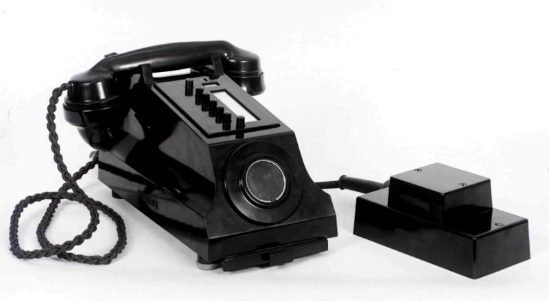
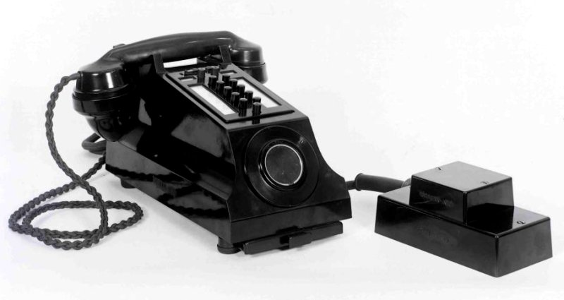
5. Telephone, Intercom, No. 1/1
This
telephone is used on installations having one exchange line and five (or exceptionally,
six) local stations. The mechanism is mounted on a metal base, measuring approximately 11in. x 5in., and is enclosed in a black, moulded cover (Cover No. 4) with a cradle rest
for the telephone handset (Telephone No. 164). On the sloping top
surface of the telephone is a row of 7 plunger keys comprising, at the top, the
exchange-line key (coloured red), followed by 5 black local-call keys and, below these,
the conference key marked 'C ' (coloured green).
The operating procedure for the keys is described in Adjacent to the keys is a window
under which a paper label bearing station numbers, etc. may be inserted via a slot in the
top edge of the sloping key panel. The labels are described in A3202 and are obtained
separately, as required. The label may be removed by first moving it. forward with the
Point of a pin inserted into a small slot provided for the purpose above the window.
The
handset of the Telephone, Intercom, No. 1/1 (Mk. 2) has a Receiver, Inset, No. 2P; that
of the Mk. 1 telephone has a Receiver, Inset, No. 1L. All new telephones will be Mk. 2
(or Mk. 2A, see par. 4) and will also include a Coil, Induction, No. 27; old telephones
of either Mark Number may contain an earlier pattern induction coil, such as the Coil,
Induction, No. 22. As issued from Supplies Dept, each telephone is fitted with a dummy
dial which, in automatic areas, may be replaced locally as required by the appropriate
Dial, Auto. S.S.No.10....
A Holder and Tray No. 2 is fitted under the base of the
telephone and the complete telephone includes a desk cord (6 feet long) terminated on a
plug fitted with a buzzer. For use at a main station, internal strapping points are
provided in the telephone to enable exchange-line monitoring or trunk - offering facilities
to he given. The use of these straps is described in C3023. The circuit of the telephone
is shown on Diagram Q(L) 131 and the wiring on Diagram Q(L) 141. The complete telephone weighs
approximately 9.5lbs.

6. Telephone, Intercom, No. 1/2A
This telephone is used on installations with two exchange lines and ten (or
exceptionally, eleven) local stations. The mechanism is mounted on a metal base and is
housed in a moulded cover of the same type and dimensions as for the Telephone, Intercom,
No. 1/1. The telephone is similarly fitted with a tray and dummy dial and includes a desk
cord (6 feet long) with plug and buzzer. The handset of the Telephone, Intercom, No. 1/2A
(Mk. 2) has a Receiver, Inset, No. 2P; that of the Mk. 1 telephone a Receiver, Inset, No.
1L. The Mk. 2 telephone also includes three resistors not fitted in the Mk. 1 type; the
function of the resistors is described in C3022.
All new telephones will be Mk. 2 (or Mk.
2A, see par. 4) and will include a Coil, Induction, No. 27; old telephones of either Mk.
No. may contain earlier-pattern induction coils, such as the Coil, Induction, No. 22.
Telephone, Intercom, No. 1/2A has 13 plunger keys, comprising two exchange-line keys
(coloured red and numbered 1 and 2) placed one above each of two rows of 5 black 'local'
keys, with the conference key marked 'C' (coloured green) placed centrally below the
others. Immediately above and associated with each exchange-line key is a trigger key
(coloured red), the functions of which are described in Q1003. A window for a 'local'
station designation label is provided adjacent to each row of keys. In addition to
internal strapping points to give exchange-line monitoring or trunk-offering, the
telephone has strapping points for use when it is fitted on a main station to enable a
local station to call the main when it is engaged on an exchange call. The use of these
straps is described in C3023. The circuit of the telephone is shown on Diagram Q(L) 231 and
the wiring on Diagram Q(L) 241. The complete telephone weighs approximately 10lb.


7. Telephone, Intercom, No. 1/2
The external appearance of this telephone is identical to that of the Telephone,
Intercom, No. 1/2A. The internal construction and circuits of the two telephones are
also very similar but a Telephone, Intercom, No. 1/2 cannot be used at a main station
which is required to be called locally while engaged on exchange calls, because the
necessary strapping points are not provided in the telephone. The circuit of this
telephone is shown on Diagram Q(L) 231 and the wiring on Diagram Q(L) 241. The handset of the
Telephone, Intercom., No. 1/2 (Mk. 2) has a Receiver, Inset, No. 2P and the Mk. 1 pattern
had a Receiver, Inset, No. 1L. Early versions of this telephone may be fitted with a
Coil, Induction, No. 22 (Mk. 1), but those of later construction include a Coil,
Induction, No. 22 (Mk. 2) [see Diagram Q(L) 231].
8. Telephones, Intercom, No. 1/1B (Mk. 2) and No. 1/2B (Mk. 2)
These telephones are used with the hearing-aid amplifier, Repeater,
Telephonic, No. 17C, and are normally produced from the Telephone, Intercom, No. 1/1 and
No. 1/2A (Mk. 2), respectively, by the addition of a, Potentiometer No. 8B and a
subsidiary terminal strip for connection to the repeater. The control knob of the
potentiometer projects through a slot cut in the side of the telephone cover. The circuits
of the telephones are shown on Diagram Q(L) 134 and Q(L) 235, respectively and the wiring on Diagrams Q(L) 144 and Q(L) 244, respectively. Diagram Q(L) 158 shows the method of connecting
the telephone to the repeater.

9. Transfer Units.
The present-day standard types of transfer unit for use on the house
exchange system are:-
Unit, Transfer, Intercom, No. 1 (Mk. 2) for use at 1st and 2nd choice main stations on
installations with one exchange line and without a non-multiple station and at a
2nd choice main station on installations having one exchange line and a non- multiple
station. See also under Unit, Transfer, Intercom., No. 3.
Unit, Transfer, Intercom, No. 1A (Mk. 2) for use at a 1st choice main
station on installations with one exchange line and a non-multiple station.
Unit, Transfer, Intercom, No. 2 (Mk. 2) for use at 1st and 2nd choice main
stations on installations with two exchange lines and with, or without, a non-multiple
station.
Unit, Transfer, Intercom, No. 3 (Mk. 1) for use together with a Unit,
Transfer, Intercom., No. 2 at the 1st choice main station on installations with two
exchange lines and a non-multiple station. The unit may also be used together with a Unit,
Transfer, Intercom., No. 1 at 2 1st choice main stations on installations having one
working exchange line but cabled for later expansion to take two exchange lines and with a
non-multiple station.
Units, Transfer, Intercom, Nos. 1, 1A and 2 (Mk. 1) may still be met with on existing
installations but will no longer be issued for new work. All such units will be converted
to Mk. 2 either in the field in accordance with Works Specification S504 or, when returned to
stores, by Factory Dept. repair.
10. Common Constructional Details
Units, Transfer, Intercom, Nos. 1, 1A, 2 and 3 are of a standard overall size, the base
being approximately 10.5in. by 7.25in. and the height 8.75in. A standard black, moulded
cover (Cover No. 5) encloses the mechanism of the unit which is mounted on a metal chassis
of the same form for all the units. The cover is located on the unit by slots in its lower
edges, at the sides, which seat on four screws on the sides of the chassis. These screws
which secure the cover in position are trapped, and cannot be completely removed from the
chassis, but when they are loosened the cover may be lifted off the unit.
Each unit includes a 25 conductor cord (Cord, Instrument, No. 25/02G, Brown, 72in.)
terminated with a plug (Plug No. 2404). The units contain exchange line and/or
non-multiple station calling and clearing indicators, with associated bell (or buzzer),
transfer keys, night-service and alarm cut-off keys and keys for switching a non-multiple
station to the exchange lines. The keys and indicators are mounted on the faceplate of the
chassis. The cover, when being lifted off, should be moved forward to clear the key
handles which project approximately i in. in front of the unit. Two recesses in the cover,
one at each side of the unit, give access to one or two press-buttons, depending on the
particular unit concerned. The functions of the keys, indicators and press-buttons are
described in C3021 and 3022. Certain of the labels indicating the key functions are
engraved on both sides and are reversible, as described in Q 3001, to enable a particular
unit to serve at either a 1st or 2nd choice main station.
11. Unit, Transfer, Intercom, No. 1
This unit, as supplied, is fitted with one 'doll's eye' indicator (labelled EXCH) for
exchange line calling and clearing. Space in the unit, with accommodation on the
faceplate, and the necessary wiring are provided for a second 'doll's eye' indicator which
may be fitted to the unit locally (and labelled EXTN) for non-multiple station calling and
clearing when the unit is to be used at a 2nd-choice main station on an installation with
one exchange line and a non- multiple station. The circumstances and method of fitting the EXTN indicator are described in C 3023. The position of the second indicator on the
faceplate is covered by a metal plate when the indicator is not fitted. Internal strapping
points are also provided to convert the circuit for alternative use of the unit at 1st or
2nd choice main stations, as described in C 3023.
The unit contains a trembler bell which can be operated by both indicators. Two
single-throw, locking lever keys are fitted, the TRANSFER key below the Exch indicator and
the ALARM OFF key below the position for the EXTN indicator. A label fitted below the keys
is engraved on both sides and is reversible to indicate either that the ALARM OFF key only
or that both keys are in use depending on the function of the unit in the
installation. The unit is fitted with one EXCH CALL press-button in the left-hand
position and a dummy button in the right-hand position. The circuit of this unit is shown
on Diagram Q(L) 132 and the wiring on Diagram Q(L) 142. The weight of the unit complete is
approximately 10.25lbs.


12. Unit, Transfer, Intercom, No. 1A
This unit is fitted with two 'doll's eye' indicators, one (labelled Exch) for exchange
line calling and clearing and one, (labelled EXTN) for non-multiple station calling and
clearing. The unit contains a buzzer (trembler bell without gong) which can be operated by
both indicators. Three lever keys are fitted on the faceplate below the indicators. The
left-hand key is a double-throw, locking key labelled ALARM OFF (NIGHT SCE) in the 'up'
position and TRANSFER in the 'down' position (when used). The centre and right-hand keys
are single-throw, locking lever keys, labelled respectively ALARM OFF and EXTN TO EXCH. The label fitted below the keys is reversible to suit the function of the unit in the
installation, as described in 3001, and internal strapping points are provided to convert
the circuit of the unit accordingly. The unit is fitted with one EXCH CALL press-button on
the left and a dummy button on the right. These units contain a special relay (BZ) for
ringing the non- multiple station. The circuit of this unit is shown on Diagram Q(L) 133 and
the wiring on Diagram Q(L) 143. The weight of the complete unit is approximately 14.1lb.


13. Unit, Transfer, Intercom, No. 2
This unit is fitted with two 'doll's eye' indicators (labelled EXCH 1 and EXCH 2) for
exchange-line calling and clearing. Space in the unit, with accommodation on the
faceplate and the necessary wiring are provided for a third 'doll's eye' indicator
(labelled EXTN) which may be fitted to the unit locally for non-multiple station calling
and clearing when the unit is to be used at a 2nd-choice main station on an installation
with two exchange lines and a non-multiple station. The circumstances and method of
fitting the EXTN indicator are described in Q 3001. The position of the third indicator on
the faceplate is covered by a metal plate when the indicator is not fitted. The unit
contains a trembler bell which can be operated by all three indicators. Internal strapping
points are also provided to convert the circuit for alternative use of the unit at a 1st
or 2nd choice main station, as described in Q 3023. Three single throw, locking lever keys
are fitted below the indicators and are labelled with a reversible label. On the unit as
supplied, the label is fitted to show only ALARM OFF against the centre key. When
reversed, the label shows TRANSFER against each outer key in addition to ALARM OFF against
the centre key.
The label is reversed to suit the function of the unit in the installation, as
described in C 3023. This unit is fitted with two press-buttons, labelled EXCH CALL 1 on
the left and EXCH CALL 2 on the right. The circuit of this unit is shown on Diagram Q(L) 232
and the wiring on Diagram Q(L) 242. The weight of the complete unit is approximately 11.5lbs.


14. Unit, Transfer, Intercom, No. 3
This unit is fitted with one 'doll's eye' indicator (labelled EXTN) for non-multiple
station calling and clearing and contains a trembler bell operated by the indicator. Three
double-throw, locking lever keys are fitted below the indicator. A single-sided label is
fitted to designate the 'down' positions of the keys as EXTN TO EXCH 1, ALARM OFF and EXTN
TO EXCH 2, respectively. The 'up' positions of the keys are designated with a reversible
label, which, on units as supplied, is fitted to designate the left and right-hand keys
ALARM OFF (NIGHT SCE 2) and ALARM OFF (NIGHT SCE 1), respectively.
Reversed, the label shows the same designations for the outer keys and in addition shows TRANSFER against the
'up' position of the centre key. The label is reversed to suit the function of the unit in
the installation, as described in C3023 and an internal strapping point is provided to
convert the circuit of the unit accordingly. These units contain a special relay (BZ) for
ringing the non- multiple station. Dummy buttons are fitted to both press-button positions
on this unit. The circuit of this unit is shown on Diagram Q(L) 233 and the wiring on Diagram Q(L) 243. The weight of the complete unit is approximately 13.5lbs.


15. Plugs
The plugs are of three types:-
Plug No. 2404, which is part of each transfer unit.
Plug No. 2404A, which is part of Telephone, Intercom, No. 1/1.
Plug No. 4001A, which is part of Telephones, Intercom, Nos. 1/2 and 1/2A.
A single type of black, moulded body is used for the three types of plug. The base of
the plug body measures 2.1in. by 3.2in. and its height is 1.5in. Two 'trapped' screws
are provided in the plug body for securing the plug to Jack No. 53 or Jack No. 54 (par.
17). A screwed cable-entry gland projects at one end for approximately 1in. A rubber
sleeve and clamping ring fitted to the cable-entry gland have previously been included as
parts of the plugs but these will in future be parts of Cords, Instrument, Nos. 25/01G,
25/02G and 38/02G , which are used with these plugs (see also Par. 16). Plugs Nos. 2404A
and 4001A include a Buzzer No. 21, which is mounted on top of the plug. The buzzer has a
separate black, moulded cover (Cover No. 3) which includes two 'trapped' screws for
securing it to the plug body. The overall height of the plug is increased by the buzzer
and its cover to 2.75in approximately. The plug points, numbered front 1 to 40, are
assembled in the form of a 'comb'. The Plug No. 4001A is fitted with all points from 1 to
40. The Plugs Nos. 2404 and 2404A are fitted only with points 5 to 28. The positions of
the plug point are such that the No.2404 and 2404A plugs may be interchanged with a Plug
No. 4001A on a Jack No. 54 without change of cabling to the jack points. By this means, it
is possible to use Telephones, Intercom, No. 1/1 initially and replace them later by
Telephones, Intercom, No. 1/2 or No. 1/2A on an installation cabled to accommodate two
exchange lines and ten stations but having initially only one exchange line and not more
than five (exceptionally, six) stations. The numbering of the plug-point terminations of
the transfer units and telephones is shown on Diagram Q(L) 152.
16. Cords
The cords used on house-exchange telephones and transfer units are Cord, Instrument, No.
25/01G, Brown, 72in. (on a Telephone, Intercom, No. 1/1 ), Cord, Instrument, No.38102G,
Brown, 72in. (on Telephones, Intercom, Nos. 1/2 and 1,/2A) and Cord, Instrument No.
25/02G, Brown, 72in. (on all Units, Transfer, Intercom). When obtained separately, the
cords will, in future, include (as part of the cord) the rubber protective sleeve at each
end with its clamping and securing rings and the cord guide at the telephone, or unit,
end. These items have been included with the cords as the large diameter, approximately 1
inch, of the cords of present manufacture makes it impracticable to fit the parts once the
cords have been made up.
Non-standard cord lengths are not stocked and requests for them should be avoided by
attention to the installation layout, as described in C3023.
17. Jacks
Jack No. 53 and Jack No. 54 are used. The former is required for all transfer units and
for Telephone, Intercom, No. 1/1 on installations cabled for a normal maximum of five
stations. The latter is required for Telephones, Intercom, Nos. 1/2 and 1/2A, but it may
be used with a Telephone, Intercom, No. 1/1 (see para. 15). The construction of the jacks
is the same for both types, except for the number of jack points fitted. The jack points
are numbered 1 to 40 and correspond to the plug points of the plugs described in par. 15. The Jack No. 53 is fitted with jack points Nos. 5 to 28 but the Jack No. 54 is fitted with
jack points Nos. 1 to 40. The jack points are of the U-point type and are mounted on a
black, moulded base (approximately 6.5in. by 3.5in.) open at the back.
 |
| Plug No. 2404A and Jack No. 53 |
| |
 |
| Plug No. 4001A and Jack No. 54 |
The height of the
jack base is 1in. and the total height of the assembly, with the plug screwed in position
on the jack, is approximately 2.5in. with a Plug No. 2404 and 33in. with Plugs Nos.
2404A and 4001A. Three slots in the base, one at each end and one at the side, are provided
for cable entry to the back of the jack. The slots in new jacks are covered by a thin
'knockout' web formed in the moulding. Jacks reissued after repair will be accompanied by
a sufficient number of small plugs Parts 1/SPL/391 to fill any previously used slots.
The
plugs will be wrapped with the fixing screws. Two wood-screws No. 8 x 1.5in. are supplied
with each jack for use when fixing the jack to a wall or other support as described in Q3001. A moulded baseplate, Part 1/SBA/4 , which may be fitted under the jack, is available
for use if the jack has unavoidably to be mounted on a damp wall. The baseplate is
approximately 6.5in. by 3.5in. and its effective thickness is approximately 3 in. Three
wood-screws No. 6 x 1in. are supplied with the baseplate for fixing it to the wall and
two screws 4 BA x 1in. for fixing the jack to the baseplate.
18. Junction Boxes
Two sizes of junction box are used and are known as Box, Junction, Intercom., No. 1 and
Box, Junction, Intercom., No. 2. Both boxes consist of a black, moulded base and cover
containing four moulded terminal strips. The covers of the No. 1 and No. 2 boxes are known
as Cover No. 1 and Cover No. 2, respectively. The No. 1 box has 30 terminals per strip and
No. 2 box 48 terminals per strip. The terminals are in two rows and are numbered 1, 3, 5,
etc., on the left, and 2, 4, 6, etc., on the right of the strip.
Each terminal provides a front and a rear screw connection and the two rows are staggered
in position so that corresponding terminals on adjacent strips may be connected together
by lengths of bare wire passed through them across the front of the strips. Wire, Copper,
Tinned, No. 18 S.W.G. is used and a number of lengths of this wire cut to bridge the four
strips is included with each box. Jumper cross-connections between terminals may also be
made with insulated wires. The portions of the terminals at the back of the strips provide
screw connections for terminating the house-exchange system multiple cable. The strips are
grooved at the back to accommodate the cable ends and a cable clamp is fitted at each end
of each strip. A bonding strip to connect together the sheaths of the cables, via the
cable clamps, is included with each junction box. The method of using the bonding strip is
described in C3023. Provision is made for cable entry at either end of the box, via four
slots in each end of the cover. The slots in new covers are filled by a thin 'knock-out'
web formed in the moulding. Old covers may be reissued with used slots (if more than two)
repaired by means of a small moulded plug, Part 1/SPL/392 for Covers No. 1 and Part
2/SPL/392 for Covers No. 2.
Three rubber feet, Parts I/SBU/6, and three wood-screws No. 10, 1.5in. are included
with each box for fixing. The overall dimensions of the Box, Junction, Intercom., No. 1
are approximately 8.75in. x 7.5in. x 2.25in. and it weighs 4lb. The Box, Junction,
Intercom, No. 2 is approximately 12in. x 8in, x 2.25in. and weighs 5lb. Labels No.
226... and Labels No. 227... may be obtained separately from the Supplies Dept., for use
with the junction boxes, as described in C3023.
 |
| Box, Junction, Intercom No. 1 (right) and
No. 2 (left) |
| |
 |
| Box, Junction, Intercom No. 2 with cover
and one terminating strip removed |
| |
 |
| Box, Junction, Intercom No. 1 with cover
removed |
| |
 |
| Box, Junction, Intercom No. 2 showing
front and rear of terminating strip |
19. Non-multiple Station Telephones
Normally a Telephone, No. 1/232... with Bell-set No. 26 or a
Telephone No. 332 is used,
but other standard alternative C.B. or automatic A.S.T.I.C. handset telephones may be used in
appropriate circumstances.
20. Extension Bell, etc
There are no special types of extension bell for use on the house exchange system. Bells
No. 56E, Bells No. 64 and other standard types are according to circumstances, as
described in C3023. Descriptions of the bells and general conditions of installation are
given in M0060. General information on lamp-calling signals is given in M0663.
21. Additional Receivers
A Receiver, Watch, No. 6L and a Hook, Receiver, X are used.
22. Labels
Particulars of labels used in junction boxes are given in par. 18.
Introduced circa 1935.
Made by Ericsson Telephones Ltd (ETL).
TELECOMMUNICATIONS INSTRUCTION
C MARKETING INSTALLATION
3 Internal
C 3021
Issue 1, Dec 1970
HOUSE EXCHANGE SYSTEMS No's 1 AND 2
Operating Procedure
1. Scope of Instruction
This instruction describes the operating procedure necessary to establish a.
connexion on the house Exchange system, and is intended as a guide for
installing staff when testing-out an installation after completion of
fitting and wiring. The information is arranged under the following headings
| Subject |
Multiple station procedure |
Non-multiple station
procedure |
| Key operation |
Paras. 3, 4 |
|
| Local calls |
Paras. 5 to 8 |
Paras. 27 to 30 |
| Conference
calls |
Para. 9 |
|
| O/G. exchange
calls |
Paras. 10 to 15 |
Para. 31 |
| I/C. exchange
calls |
Paras. 16 to 19 |
Paras. 32 to 34 |
| Transfer of
exchange calls |
Paras. 20 to 23 |
Para. 35 |
| Special
facilities |
Paras. 24 to 26 |
|
| Night service |
Para. 36 |
Para. 37 |
| Local calls
between multiple and non-multiple stations under night- service
conditions |
|
Para. 38 |
For detailed circuit operation, see
C3022.
2. Terms
The terms "Multiple station" and "Non-multiple station," respectively,
replace the terms "Internal Extension station" and "External Extension
station" employed in the previous issue of this Instruction.
MULTIPLE STATION PROCEDURE
3. Key Operation
The mechanical arrangement of the keys on "Telephones, Intercom Nos. 1/1 and
1/2" is such, that when depressed consecutively (except while conference key
"C" is depressed) only one key may remain fully operated at any time. If a
local key is in the operated position, the depression of a second local key
completely restores the first. If, however, the conference key is first
depressed, or is depressed after only one local key has been depressed, all
the remaining keys may subsequently be depressed simultaneously, and will
remain operated (in the speaking position). The conference key and all local
keys held by it will be released if an exchange key is depressed. or if the
handset telephone is replaced on its rest. If an exchange key is in the
operated position, the depression of a local key or of the second exchange
key will partially release the first key, which will then take up a "hold"
position (see par. 13).
4. Key re1ease
When any key (or all of the keys) has been operated, replacement of the
handset on its rest automatically restores all keys to normal. On telephones
having two exchange keys, i.e., "Telephones, Intercom., No. 1/2", either
exchange key may be released from the "hold" position by operating its
associated trigger - RELEASE - key without replacing the handset and without
releasing a local key or the other exchange key, one or the other of which,
in "hold" circumstances, will be in the operated position at the time. The
release of an exchange key by means of the trigger key is effected by
pulling the trigger towards the exchange key until a "click" is heard
denoting the release of the exchange key mechanism. The trigger key will not
release an exchange key from the fully-operated position.
5. Local call - Called
station free
A call from one multiple station to another or to a non-multiple station is
made by lifting the handset at the calling station and fully depressing the
plunger key adjacent to the required station number. In the fully depressed
position, this key completes a circuit for operating the telephone buzzer at
the called station. When pressure on the key is released, the key
automatically takes up the speaking position. The call is answered by the
handset being lifted at the called station and conversation is then
possible.
6. Called station
engaged on Local call
Local calls are not secret; if, therefore, the called station is engaged on
a local call, the calling station will break-in on the conversation.
7. Called station
engaged on exchange call
Except as described in par. 24, if the called station is engaged on an
exchange call, the buzzer at the calling station operates when the key for
the called station is fully depressed. This serves as an engaged signal to
the calling station and the conversation of the called station on the
exchange line cannot be broken into or overheard.
8. Called station
holding exchange line
If the called station is holding an exchange line, while engaged on a local
call, the calling station buzzer will be operated (as described in par. 7)
but the called station's local call will be broken into and the calling
station can listen to the conversation.
9. Conference call
When it is desired to make a. conference call, the stations which will
participate are first called individually, as described in par. 5. When the
attention of these stations has been obtained, the conference key at the
calling station is depressed, followed in succession by the keys
corresponding to the stations concerned. The. conference may then proceed.
The conference connexion is released completely by replacing the handset on
its rest, or by depression of an exchange key. Therefore, if a station which
has set up a conference call makes or receives an exchange call, the
conference call is automatically terminated. Any of the called stations may
break away from the conference to make or receive an exchange call in the
normal manner, as described in pars. 11 to 13, and subsequently, may return
to the conference by momentarily depressing the plungers on the handset
rest, to release the exchange key. If a called station on conference calls
another local station, by depressing the appropriate key, conversation
between the two will be overheard by other parties to the conference. It is
not possible for the calling station to release stations individually from a
conference call.
10. Outgoing exchange
calls - From stations having full facilities
Multiple stations with full facilities have direct access to exchange lines,
as described in the following pars. 11 to 13.
11. Exchange line
engaged test
Except as described in par. 25, an exchange line may be tested by depressing
the relevant exchange key without removing the handset from its rest. If the
exchange line is engaged, the calling station buzzer will operate. Under
these conditions, the exchange key releases automatically when pressure on
it is removed, [The engaged test also operates on engaged exchange lines if
the exchange key is depressed after the handset has been lifted. The
exchange key then remains in the operated position until the handset is
replaced or until another key is depressed.] For procedure at a main station
having visual exchange-line engaged signals, see par. 26.
12. Exchange line free
If a buzzer signal is not received on depression of an exchange key, the
exchange line is free; connexion to the exchange Line may then be obtained
by lifting the handset and depressing the exchange key. This operation calls
the exchange, if it is manual, or if the exchange is automatic, the caller
receives dialling tone and may proceed to dial the required number.
13. Holding exchange
call while snaking a local call
If, during the progress of an exchange call, the calling station desires to
speak to one of the local stations, the depression of the local key
corresponding to the wanted station automatically releases the exchange key
to an intermediate position, in which a "hold" condition is presented to the
exchange line. At the termination of the local call, the exchange key may
again be fully depressed and the exchange-line conversation resumed.
14. Holding one exchange
call while making a second exchange call-On installations with two exchange
lines, if a station (while engaged with one exchange call) desires to make a
call over the second exchange line, the depression of the second exchange
key releases the first key to the hold" position At the termination of the
second call, the first call may be resumed by again depressing the first
exchange key; this, in turn, releases the second key to the "hold" position.
The second key may then be completely released by means of its associated
trigger key (par. 4).
15. Calls from stations
having restricted facilities
It is not possible to obtain direct access to exchange lines from stations
with restricted facilities. Such stations desiring to make an exchange call
must first call the main station, as described in par. 5, and advise the
main station attendant of the exchange and number required. If the call is
to be permitted, the caller is asked to replace the handset on its rest and
await recall from the main station. The call is then set up by the main
station attendant and transferred to the calling station, as described in
par. 22.
16. Incoming exchange
calls, and main station procedure - Control by main station
All incoming exchange calls are first received at the main station (or other
multiple station acting as main station). The incoming calling signal
operates an indicator in the unit equipment ("Unit, Transfer Intercom., No.
1, 1A or 2") fitted at the main station. An audible signal (by bell or
buzzer) is also given. The audible signalling apparatus, when not required,
may be disconnected by means of the ALARM OFF key on the transfer unit On
installations with two exchange lines each line has an individual indicator,
but a common audible alarm serves both. The main station attendant answers
the call by lifting the telephone handset and depressing the appropriate
exchange key. If the call is for another station it is transferred to that
station as described in pars. 20 to 22 or par. 32.
17 Control by 2nd-choice
main station
On installations having a 2nd choice main station all the functions of the
1st-choice station (except as regards non-multiple station calls, the
procedure for which is given in par. 33) may be transferred to the
2nd choice station by means of the TRANSFER key or keys on the 1st choice
main station transfer unit. Incoming exchange calls are received at the
2nd choice main station and dealt with in the same manner as described in
par. 16.
18. Control by multiple
station with extension bell
At a multiple station arranged for the receipt of exchange calls, the
calling signal is received on an extension bell (or equivalent device) from
the main station transfer unit. On installations with two exchange lines,
one extension bell serves both lines and it is therefore necessary for the
attendant to test for the calling line. This is done by lifting the handset
and depressing one of the exchange keys or each exchange key in turn. [No. 1
exchange line should be tested first to minimize the number of occasions on
which a false call will be given to the public exchange]. If the call is for
another station, it is transferred as described in pars. 20 to 22 or par.
32.
19. Holding one exchange
call while receiving a ,second exchange call
On an installation with two exchange lines, if the main station (or station
serving as main) is engaged on one exchange call, another exchange call
signalled on the second line may be answered by depressing the second
exchange key, thus releasing the first exchange key to the "hold" position
(as described in par. 13). If the second call is for another station, it may
be transferred as described in pars. 20 to 22 or par. 32. Resumption of the
first call and release of the second call may be effected as described in
par. 14.
20. Transfer of exchange
calls - Station with full facilities
An exchange call, originated (or received) at a main station or multiple
station may be transferred to another multiple station with full facilities.
At the Station transferring the call, the local key corresponding to the
required Station is depressed, thus releasing the exchange key to the "hold"
position (see par. 13), and the required station i asked to "pick up" the
call on the exchange line concerned. To do this, the appropriate exchange
key is depressed at the called station, whereupon, the buzzer operates at
that station and buzzer tone is passed back to the first station where it is
heard in the handset receiver. The handset at the first station is then
replaced on its rest. This causes the buzzer at the called station to stop
operating and the exchange call to be connected automatically at that
station. The transfer is then complete.
21. Station engaged with
one exchange call while holding another
On installations with two exchange lines a station, while engaged with one
exchange call and having made or received a second exchange call (as
described in par. 14 or par. 19) may transfer one of the calls to another
station with full facilities, while holding the first. call. The procedure
for transferring the call is as described in par. 20, except that on receipt
of the buzzer tone from the station "picking up" the call, the appropriate
exchange key at the first station is released by means of the associated
trigger key (see par. 5) and not by replacing the handset on its test. The
call held may then be resumed by again depressing the relevant exchange key
or it may, in turn, be transferred to another station (as described in par.
20).
22. Station with
restricted facilities
A main station may transfer an exchange call to a multiple station with
restricted facilities by proceeding as described in par. 20, except that on
receipt of the buzzer tone from the other station, the main station
attendant will depress and hold down the EXCH CALL button (on the main
station transfer unit) corresponding to the exchange key on the telephone,
then release the appropriate exchange key on the telephone, and lastly, will
release the EXCH CALL button. The EXCH CALL button must be held operated
until the exchange key on the telephone has been released. The transfer of
the call is then complete. Any station, other than the main station,
desiring to transfer an exchange call to a station with restricted
facilities must first transfer the call to the main station by the procedure
described in par. 20.
23. Transfer of exchange
calls to non-multiple station
The main station procedure for transferring an exchange call to a
non-multiple station is described in par. 32. A multiple station, other than
a main station, desiring to transfer an exchange call to a non-multiple
station must first transfer the call to the main station by the procedure
described in par. 20.
24. Special facilities -
Multiple station calling main station engaged on exchange call
Where the facility is given (only on installations with two exchange lines),
to call the main station while it is engaged on an exchange call, the
calling station buzzer does not operate when the calling station fully
depresses the local key associated with the main station, as described in
par. 6; instead, the main station buzzer operates as if the station were
disengaged. To answer the call, the main station attendant depresses the
local key associated with his own station. This releases the exchange key to
the "hold" position (see par. 13) and connects the main station handset to
the local calling line. If it is then desired to transfer the held exchange
call to the calling station, the key associated with that station on the
main station telephone should be depressed and the call transferred, as
described in par. 20. If the procedure is not adopted, buzzer tone will not
be heard in the main station receiver, when the calling station depresses
the relative exchange-line key, and the main station attendant will have no
indication that the transfer of the call is in process.
25. Exchange-line
monitoring or trunk-offering facility
Where the facility is given for a station to monitor on exchange lines
(normally limited to a 1st choice or 2nd choice main station) the exchange
line engaged signal, as described in par. II, is not given; instead the
calling station with the monitoring facility may break-into, or listen to,
an exchange call proceeding at another station on the system. This
facility is for limited use only, see C3001.
20. Visual
exchange-line-engaged signal
On installations where the facility is given for the main station to have
visual exchange-tine-engaged signals, these are given by the indicators in
the main station transfer unit ("Unit, Transfer, Intercom., No. 1, 1A or
2"). With this facility, it is not necessary for the main station attendant
to test exchange lines by depressing the exchange keys (as described in par.
ii) because the presence, or absence, of the indicator signal will indicate
whether the exchange line concerned is engaged or free.
NON-MULTIPLE STATION PROCEDURE
27. General
Except under night service conditions (as described in pars. 36 to 3), all
calls originated by a non-multiple station and all incoming exchange calls
for such a station are passed via the main station and require the services
of the main station attendant to complete the connexions. Local calls made
to the non-multiple station from multiple stations, although passing via
equipment at the main station, are made without the intervention of the main
station attendant.
28. Non-multiple station
calling main station
To gain the attention of the main station, the handset at the non-multiple
station is lifted and this results in the operation of the extension
indicator (and associated alarm bell or buzzer) in the main station transfer
unit, ("Unit, Transfer, Intercom., No. 1A or 3"). To answer the call, the
main station attendant lifts his telephone handset and depresses the local
plunger key corresponding to the non-multiple station.
29. Local calls -
Outgoing
The non-multiple station first calls the main station (as described in par.
28) and advises the attendant of the local station required. The main
station attendant then calls the wanted station and, in turn, asks the
latter to call the non-multiple station (as described in par. 5) i.e.
the call is reverted.
30 Local calls -
Incoming
Incoming calls are signalled at the non-multiple station in the normal way
on the magneto bell associated with the non-multiple station telephone.
Local calls to the non-multiple station are made directly (as described in
par. 5) and are answered at the non-multiple station by lifting the
telephone handset.
31. Outgoing exchange
call - Control by main station
The non-multiple station first calls the main station as described in par.
28 and either asks to be connected to an exchange line or advises the
attendant of the exchange and number required. Except as described in par.
26, the main station attendant tests the exchange lines for a free line (see
par. 11). When a free line has been obtained, the attendant may operate the
EXTN TO EXCH key on the main station transfer unit to connect the
non-multiple station to the exchange line so that the non-multiple station
may proceed to set up the call. Alternatively, the main station attendant
may set up the exchange call and, then, transfer it to the non-multiple
station (as described in par. 32). On completion of the call, when the
non-multiple station replaces the handset on the telephone, the extension
indicator on the main-station transfer unit operates to give a clearing
signal to the attendant, who then restores the EXTN to EXCH key On the
transfer unit ("Unit, Transfer, Intercom., No. 1A or 3"). See par. 33 for
control by a 2nd choice main station.
32. Incoming exchange
call - Control by main station
As described in par. 16, all incoming exchange calls are first received at
the main station or other multiple station acting as main station. If an
exchange call is to be transferred from the main station to a non-multiple
station, the main-station attendant calls the non-multiple station (par. 5)
and then operates the EXTN TO EXCH key on the transfer unit. The subsequent
procedure at the main station is as described in par. 31. For control by a
2nd choice main station, see par. 33.
33. Control by
2nd-choice main elation
If control has been transferred to a 2nd choice main station (by operating
the TRANSFER key or keys at the 1st choice main station) the 2nd choice
station will receive, the calling signals from the non-multiple station but
the facility for switching the non-multiple station to an exchange line will
remain at the 1st choice main station. Therefore, if the non-multiple
station desires an exchange call, the 2nd choice main station attendant must
go to the 1st choice main station to carry out the necessary switching. If
the attendant remains at the 1st choice station until the call terminates,
the control must be reverted to the 1st choice station, by restoring to
normal the TRANSFER key (or keys) so that the clearing signal for the
non-multiple station call may he received there. If the attendant returns to
the 2nd choice station to await the clearing signal, he must an back when he
receives it, to the 1st choice main station to restore the EXTN TO EXCH key.
34. Control by a
multiple station with extension bell
When a multiple station, fitted with an extension bell from the main Station
transfer unit, is in control on an installation equipped for one exchange
line only but having a non-multiple station, the exchange and non-multiple
station calling signals will be received on the same bell. In such cases,
the non-multiple station calling signal will be a continuous ring on the
bell whereas the exchange calling signal will be intermittent. The
attendant, desiring to connect the non-multiple station to the exchange line
or to transfer an exchange cull to the non-multiple station, must go to the
main station and proceed as described in par. 31 or 32. On installations
with two exchange lines and a non-multiple station, one extension bell
serves both exchange lines see per. 18) but the non-multiple station calling
signals are extended to a separate bell.
35. Recalling main
station while holding exchange call; transfer of exchange call to multiple
stations
A non-multiple station user engaged on in exchange call and desiring to call
the main station without releasing the call, may do so (except for certain
outgoing calls via automatic exchanges as described below) by "flashing,"
i.e., by repeatedly depressing and releasing the plunger (or plungers) of
the handset rest on his telephone so as to cause the intermittent operation
and release of the extension indicator at the main station. The attendant at
the main station lifts his handset, depresses the exchange key of the
exchange line concerned and, then, restore, the EXTN to EXCH key on the mum
station transfer unit, thus transferring the exchange line to the control of
the main station; the attendant then calls the non-multiple station, by
depressing the associated local key, and asks the reason for the recall, if
required, the call may than be transferred to another station (am described
in pure. 20 to 22). Alternatively, the call may be reconnected to the
non-multiple station by re-operating the EXTN to EXCH key. If the
non-multiple station recall signals are received at a 2nd-choice main
station (see par. 33 or at a multiple station with extension ball (see per
34), the attendant must go to the 1st-choice main station to answer the
call. If the non-multiple station is engaged on an exchange call which has
been originated at the House Exchange system by direct dialling (either from
the non-multiple station itself or from another station on the system and
subsequently transferred to the non-multiple station), the non-multiple
station cannot recall the main station without releasing the exchange call.
NIGHT SERVICE
36. Multiple station
If a multiple station is arranged to receive exchange calls on night
service, the calling signals from the main station transfer unit will be
received on an extension bell. The calling signals will be given
simultaneously at the main station and at the multiple station, and may be
answered at either.
37. Non-multiple station
The non-multiple station may be permanently switched to an exchange line
during the night, by the operation of two keys, the EXTN to EXCH key and the
ALARM OFF (NIGHT SCE) key, on the main station transfer unit ("Unit,
Transfer, Intercom., No. 1A or 3"). As a warning against a mis-operation an
indicator signal is given if only one of the two keys is operated or if
other keys are also operated. Under night service, the non-multiple station
may make (and receive) exchange calls directly over the night-service
exchange line in the normal manner appropriate to a direct-exchange-line
user. Multiple stations on the installation may use the night-service
exchange line when it is not in use by the non-multiple station, but calls
so made will not be secret from the non-multiple station. Similarly, a
night-service call made by the non-multiple station will not be secret from
the multiple stations.
38. Local calls under
night service conditions
On installations with only one exchange line, local calls between a
non-multiple station on night service and multiple stations on the system
cannot be made. On installations with two exchange lines, a multiple station
may call the non-multiple station on night service, via the public exchange
over the second exchange line. Similarly, the non-multiple station may call
a multiple station (if the main station is attended to receive the call) via
the public exchange over the second exchange line.
|