Kiosk No. 4 (K4) | |||||||
|
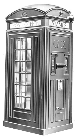
The standard No. 4 kiosk was designed by the British Post Office Engineering Department on the basis of the successful No. 2 Kiosk and received final approval in 1927. It was constructed in cast iron the sections of which were prepared for erection on site. The Kiosk was considerably larger than any of the other types and had overall dimensions of 9 feet 3 inches by 4 foot 4.5 inches by 3 foot 4.5 inches. Painted vermilion outside and a flame colour inside, it gained the nickname of 'The Vermilion Giant'. Only 50 of these kiosks were ever made, at an original cost of £50 6s 9d each. They were intended to be a miniature Post Office, located where no such facilities existed or where expense prevented a sub-post office from being built. Unfortunately these kiosks were unsuccessful. Many people complained about the noise of the stamp machine while they were using the telephone and the rolls of stamps in the machine tended to become gummed in damp weather. For these reasons, and because of the high unit cost, the Post Office decided in 1935 that no further kiosks of this type would be installed. Only one batch of Kiosks were produced and this was in 1927, by the Carron Company. But confirmed erection dates are difficult to find. A kiosk K4 was erected in Warrington in 1929 and it may be that the others followed, probably not in great numbers and with extended timescales. Cast iron structure incorporating a posting box and stamp selling machine (Engineering Department) (1928). Coloured inside and outside in Red 539 with underside of roof painted in white enamel. A Kiosk No. 4 was provided at Southend and was one of 50. Southend Corporation applied for a combined telephone and stamp vending machine on Pier Hill. They subsequently complained that the Kiosk was unsatisfactory. After the experiment had finished no more kiosks of this type were ordered. The GPO also appeared to have experimented with these Kiosks and there is a picture lower down this page showing a cable cabinet installed in the rear panel. Uses Hinges, Brass No. 2 on the door (6" x 3"). Drawing - 8849 Click here for an article on the prototype Post Office kiosk Taken from BT archives How many are left and their locations
Kiosk No. 4 details
Prototypes
Made of plywood, this prototype was probably pictured in the courtyard outside the GPO North building, London Click here for an article on the prototype post office kiosk An Extract from SECTION IV - KIOSK No. 4 191. Kiosks No. 4 are constructed of cast iron and are a modification of Kiosk No. 2 designed by Sir Giles Gilbert Scott, R.A. No. 4 embodies a telephone Call Office, a letter box and a pair of automatic stamp-vending machines. 192. General Design - Diagram E.C. 1354 illustrates the general design and appearance of the kiosk and gives its principal dimensions. 193. Advice Notes - The provision, recovery or removal of a Kiosk No. 4 will be covered by the issue of an Advice note. Precedent Secretarial authority is necessary before the issue of an advice note for the installation of a Kiosk No. 4. 194. Transportation - The various parts of the kiosk are forwarded packed partly in four cases and partly in straw bundles, usually 12 in number. The cases are the property of the Contractor who supplies the kiosk and after they have been unpacked should be returned forthwith. Normally the unpacking should be carried out immediately after receipt but, in view of the number of small parts in one of the cases measuring approximately 42 inches by 21 inches by 16 inches, local conditions may render it advisable to defer the unpacking until near the time of erection. Whatever the circumstances, however, the return of the eases should not be avoidably delayed. 195. To economize in the cost of packing cases, a requisition for a Kiosk No. 4 should be prepared and forwarded to the Stores Department immediately Advice Note authority is received but a note must be inserted in the Remarks column indicating that further advice will be given in regard to the delivery of the kiosk. The Stores Department should be advised that delivery can be accepted, when, but not before, the agreement with the Local Lighting Authority for leading in the lighting service has been completed and the date on which the telephone line work will be finished is known definitely. 196. Selection of Site - The Sectional Engineer should co-operate with the Controller, London Telephone Service, or District Manager in selecting the site (see Wayleave Regulations 485B and Telephone Service Instructions, Division G, Section G3, paragraph 20) and the following points should receive due consideration:-
197. General Description - Kiosk No. 4 comprises 49 parts viz
:- 199. The partition separates the compartment accessible to the public from the compartment occupied by the stamp vending machine and the letter box fixed to the back panel. 200. Screws and bolts for the assembly of the parts for fixing the wallboard and conduit for the protection of telephone and electric light leads are supplied with the kiosk. 201. The stamp vending machine should be obtained from the Controller, London Postal Service, or the Postmaster. 202. The cast-iron units of the, kiosk are very easily fractured and should therefore be handled with great care. They should be laid flat during storage and should be stored under cover to prevent rusting. 203. Erection - As a Kiosk No. 4 weighs 1.5 tons an "A" quality concrete foundation, see T.I. XIV, Part I, Section 3 (1), of a uniform thickness of from 4 inches to 6 inches in depth must be provided on unpaved ground. A concrete foundation of the same description is also necessary in order to provide a horizontal base for the kiosk where the site chosen is on a decided slope. The foundation should be sunk into the slope and it should be uniform in depth. When necessary, a channel should also be provided on the upper side of the foundation to deflect rain water from the kiosk. A concrete foundation is not necessary when the site chosen is on level ground paved with slabs of natural or artificial stone. 204. If the kiosk is to be erected on ground having a considerable slope, special consideration should be given to the position of the sill frame in respect of the side on which the door will be fitted and, where the door would otherwise be considerably higher than the ordinary ground level, the depth to which the concrete foundation is sunk into the slope should be sufficient to make the step into the kiosk not greater, or but little greater, than the depth of the sill frame. 205. Where it is necessary to provide a concrete foundation, it should be put in before any part of the kiosk is taken to the site. When laid, it should be protected from the action of frost, shielded against too rapid drying by exposure to sun or wind, and guarded for at least forty-eight hours in order that it may set thoroughly before erection is proceeded with. 206. Earth Connexion - The kiosk being constructed of east iron, it is necessary to provide an Earth connexion from the framework to an Earth plate or other efficient earthing device. If an Earth plate is provided, it should be sunk in the vicinity of the site but not below it or so nearly adjacent to it that subsidence of the ground on which the kiosk is to stand may be rendered possible. An Earthing bolt to which an Earth wire must be securely connected in every case is provided in the back panel of each kiosk. 207. Leading-in - Telephone and electric light services must be led into the kiosk through the foundation in the positions indicated in diagram E.C. 1348; the former towards the right-hand side of the partition so that, on emerging from the underground pipe, they may be continued in G.I. conduit fixed to the left of the right-hand bosses provided for fixing the wallboard, and the latter on the right-hand side of the kiosk, as viewed from the front, near the door opening so that they may be continued vertically via G.I. conduit to the electric light fittings as shown in diagrams Sketch P. 1008 or Sketch P. 1016. Arrangements must therefore be made for the underground telephone and electric light service pipes to he in situ before a concrete foundation is laid or where a concrete foundation is unnecessary before the erection of the kiosk is started. The position of the base (sill frame) must be carefully marked out on the site and the service pipes must be laid to suit the position to be occupied by the G.I. conduit. 208. Erection of the super-structure must start sufficiently early to permit of the job, including the filling-in of the sill frame with concrete, see paragraph 227, being completed in the course of one day. Kiosk No. 4 must not be left with the sill frame unfilled. 209. Details of the kiosk are shown in Diagram E.C. 1348 and, for guidance during erection, the sections are numbered upwards starting at the corner of the base at the right-hand side of the door opening. Corresponding numbers are marked on the sections all the way up. 210. The foundation having, been prepared, the sections should
be erected, fitted and assembled in the following manner and order and
in accordance with the subsequent instructions:- 211. When the sill frame is placed in position, the four pieces of steel plate supplied with the kiosk must be placed under the four levelling bolts and the frame must be levelled by using a spirit level after the bolts have been adjusted. When the site chosen is on pavement which slopes slightly but not to such an extent as to necessitate a concrete foundation, see paragraphs 203, 204 and 205, it may be necessary, in order to obtain the required horizontal position, to pack up the steel plate with material obtained locally. 212. All the joints and the ironwork which are inaccessible after the erection of the kiosk has been completed must be painted as the work of erection proceeds with a coat of lead coloured paint. This applies particularly to:-
213. After being painted, all the joints except those between the baffle plates and top panels and between the top panels and sign frame must be liberally served with putty. 214. The centre plate should be hinged and secured to the under side of the ceiling plate before erection. 215. Each baffle plate and top panel should be screwed together before erection. Prior to assembling, the joints, having been painted, should be thinly served with putty. The screws securing the baffle plate and the top panel together should be tightened up while the paint is still wet and the putty is soft in order to ensure that a water-tight joint is made. 216. The joints between the top panels and the sign frame should also be served with thin putty after they have been painted. 217. The ceiling plate, top panels, baffle plates and top cover must be well painted on the inside before erection or before the top cover is fixed in position. 218. The screws in the vertical members, transom rails and the sign frame should not be driven right home during the course of erection until the members referred to have been assembled. All the screws, with the exception of those in the corner pillar on the hinged side of the door, must then be tightened up and any surplus putty, extruded from the joints, removed. 219. An ordinary lath of a width equal approximately to the thickness of the door should be tacked along the full length of the bottom edge of the door to prevent the splintering of the door during erection. When placed in position, the door should be wedged up, as high as possible on the hinged side while the hinges are screwed to the corner pillar. The door-closing spring may be attached to the transom rail before the door is placed in position but before it is connected to the door or the restraining strap is secured to the corner pillar the lath should be removed from the bottom of the door and the screws in the corner pillar should be tightened up while the door is being tested to ensure that it hangs freely. The fitting of the restraining strap and door-closing spring may then be completed and the latter adjusted to function properly. 220. When the door has been hung and before the sill frame is filled in with concrete, see paragraph 221, the perpendicularity of the kiosk should be tested by means of a plumb bob and line and any adjustment that may be necessary should be made to the levelling screws in the sill frame or to the packing beneath them. All visible projecting screw ends must afterwards he out flush and smooth with a sharp cold chisel. Care should be exercised in doing this work in cold weather particularly at the corners of the transom rails. 221. When the erection of the kiosk has been completed, the sill frame should be filled in to within one inch of the curved section with "A" quality concrete which should be carefully punned under the flanges and corners of the frame. The concrete should be allowed a few hours to set and then the floor of the kiosk must be finally completed with a granolithic surface flush with the bottom of the curved section of the sill frame. The finished floor should be floated smooth and given a slight fall from back to front. The granolithic material should be composed of: 1 part Cement; 1 part Sand; 2 parts graded 0-0.25 inch granite chippings. 222. The door should be secured to prevent access to the kiosk until the floor has thoroughly set. 223. Signs - In ordinary circumstances, four opal signs, one Glass No. 25, 2 Glasses No. 26, and one Glass No. 27, must be fitted but where the kiosk is erected in a position in which the side is flanked by a fence, wall or building of greater height than the kiosk only one Glass No. 26 is required and the other should be replaced by a piece of 21oz. clear glass 28.25 inches by 5 inches purchased locally and fitted in the panel adjacent to the fence, wall or building. The signs will be illuminated at night be means of a light (normally an electric lamp) fitted inside the kiosk. 224. Maintenance - It is very important that the door should be
tested at frequent intervals to ensure that it is closed automatically
by the door-closing spring and that the restraining strap prevents it
opening to a greater angle than one of 75 degrees which is equivalent to
an opening of 2 feet 7.5 inches measured from the door jamb to the edge
of the door. In Engineering Sections in which functional
arrangements exist the workman responsible for the maintenance of the
apparatus should make any necessary adjustments to the door spring and
should draw attention to any stretching of the restraining strap that
may require to be rectified. 226. Tools - The following tools not normally included in tool
kits are necessary for the erection of Kiosks No. 4:- 227. The tool kit should include an extra large screw driver, a tommy bar tapering from inches upwards, an adjustable spanner, a plumb bob with line and a spirit level. 228. Lighting - Details of the lighting arrangements and instructions regarding the maintenance of fittings are given in Circular Power 46, Engineer-in-Chief's. Monthly List, June 1930, which deals with the general question of kiosk lighting. 229. Decoration. With the Postmaster General's approval, the following procedure is laid down to ensure the maintenance of a creditable standard of decoration of cabinets and kiosks. 230. Where the P.O. Engineering Staff includes no skilled painter, the decoration work should normally be carried, out by tradesmen painters engaged for the purpose by the Department or under contract, cabinets and kiosks being grouped for this purpose so far as is practicable. 231. When, however, the foregoing procedure would be attended by serious inconvenience or would be unduly costly, the work may be entrusted to P.O. workmen provided that men are available who are competent to do the painting with credit to the Department. If doubt exists as to the competency of the P.O. workmen, outside labour should be employed. 232. When the work is put out to contract, a specification should be prepared in accordance with these instructions. 233. Painting, Washing and Rubbing down of new kiosks - The whole of the iron work must be washed down with warm water to which has been added sufficient soda to remove all grease and dirt particularly on those parts which have been handled in the course of erection. The whole of the work must then be washed with clean water to remove any traces of soda and finally wiped dry. 234. When it is desired to proceed with the painting immediately after washing and drying, a small quantity of clean turpentine must be well brushed into the recesses to remove any remaining water or dampness. 235. All knots must be well coated with knotting before the priming coat of paint is applied to the woodwork. 236. Painting Internally - Kiosks must be painted internally with 1 Priming Coat and 1 or 2 Coats of Flame Coloured Finishing Paint. One coat of finishing paint should usually suffice but a second coat may be given to secure a satisfactory appearance. 237. Painting Externally - Kiosks must be painted externally with 1 Priming Coat; 1 Undercoat; 1 Coat of Special Red Finishing Paint; 1 Coat of Varnish. 238. Repainting Kiosks - Kiosks which have previously been painted and; the paint of which is in good condition must be washed down internally and externally and given one undercoat externally. The inside must then be given one or two coats of Flame Coloured Finishing paint while the outside must be finished with one coat of Special Red Finishing paint and one coat of Varnish. One coat of Flame Coloured Finishing Paint normally suffices but a second coat may be given to secure a satisfactory appearance. Where the paint work has been damaged it must be touched up in the damaged places before being re-painted. 239. Quantities and Descriptions of Paint - The quantity and description of paint, etc., to be used for the decoration of Kiosks No. 4 are given below and supplies can be obtained from the Stores Department. Exterior 240. The Paint, Lead Colour, is required for painting such
portions of the kiosk as will be inaccessible after the erection of the
kiosk has been completed, see paragraph 212. 242. Redecoration - Great importance is placed upon the advertisement value of kiosks to the Post Office. As, owing to the varying atmospheric conditions to which kiosks are exposed, it is impossible to lay down a definite period for redecoration, arrangements should be made for a periodical inspection by a competent officer. In no circumstances should the kiosks be allowed to have a dilapidated appearance. 243. Wallboard - The partition in the kiosk is arranged for a wallboard 53 inches by 30 inches to be mounted directly thereon by means of screws which are supplied with the kiosk. These screws should be left in position by the kiosk erectors or handed over to the foreman of the fitting staff. The telephone coin-collecting box and notices should be fixed to the wallboard. 244. Apparatus Lay-out - The general arrangements of the apparatus and notices should be strictly in accordance with the lay-out plans and conditions specified in T.I. XXXVI, Part 1. 245. Directory Shelf - A shell to be obtained under the Rate Book description "Desk No. 15" (Drawing 9196) which includes the necessary brackets (Brackets, Shelf No. 2 - Drawing 9855) for fixing should be fitted on the Wallboard in Kiosk No. 4 as shown on Diagrams E.C. 1401, 1402, and 1403. The directory should lie flat on the shelf and should be secured by the cord supplied with it. The cord should be passed through the hole in the desk and fastened to one of the desk brackets. Additional Pictures
Front
Rear
Restored example at Avoncroft Museum
K4 at Warrington
Experimental Kiosk No. 4 with external plant (cable terminations) accessible via a rear door.
|
|||||||
Last revised: July 22, 2025FM |
 The
Kiosk No. 4 was first
proposed in 1923 and a prototype was erected in Bath in 1926 (see
pictures below). In
addition to the telephone it contained facilities for buying stamps and
posting letters.
The
Kiosk No. 4 was first
proposed in 1923 and a prototype was erected in Bath in 1926 (see
pictures below). In
addition to the telephone it contained facilities for buying stamps and
posting letters.


