KEYSENDER No. 1 | |||||||
| TELECOMMUNICATIONS INSTRUCTION C MARKETING AND INSTALLATION 3 Internal E5029 Issue 1, June 1978 THE SELF CONTAINED KEYSENDER No. 1 GENERAL It is introduced to the customer as an alternative to the conventional rotary dial on PMBX's 1A, 1B and PMBX 4/1A installations. DESCRIPTION The Key Unit No. 4/1A is mounted in place of the operators dial. It has a 3-3-3-1 key format integral with a Cancel Key marked "-" and an amber supervisory lamp. Keyed in numbers will be stored in the sender 9B-1 which is located within the switchboard and has a capacity of 16 digits. The sender will transmit loop disconnect pulses to line (at 10pps) as soon as the first digit has been keyed-in. The amber supervisory lamp will, by remaining alight, indicate that stored digits are being transmitted. The keysender, utilises the PMBX power supply, and therefore keysenders fitted to PMBX 4/1A installations powered directly from the mains will become inoperative under mains fail conditions. Keysenders on PMBX 1A, 1B, and PMBX 4/1A with standby power will remain operative so long as there is sufficient charge in the floated battery system provided on these types of installations. On PMBX 1A and 1B installations a Voltage Regulator Unit 13A is required. This is necessary because there is no voltage regulator circuit on these installations. It should be noted that a faulty SC Keysender No. 1 cannot be changed by the PBX Operator. FIELD OF USE The SC Keysender No. 1 may be provided on installations where two non- multiple PMBX 4/1A are installed provided the Long Cord Kits (Kits 227B) are fitted to each position. Due to operating reasons it is generally undesirable to mix dial and Keysender No. 1 at one installation, so where keysending facilities are requested it is recommended that the SC Keysender No. 1 is provided at each position.
Sender No. 9B-1 OPERATION
It is not necessary to pause between key operations while a digit is pulsed out. The Amber supervisory lamp glows while these pulses are being sent. Do NOT restore the 'Dial/Ring Back or the Speak/Dial keys to normal until the Amber lamp has gone out. If a wrong number has been keyed press the Cancel Key (marked -) withdraw the calling cord for at least two seconds and set the call up again. INSTALLATION S(W) 2206A applies to PMBX's 1A and 1B. S(W) 2207A applies to PMBX 4/1A. STORES ITEM QUANTITY (PER POSITION) The following stores are required per switchboard position for the keysender conversion on PMBX 1A and 1B installations-.- ITEM QUANTITY (PER POSITION)
|
|||||||
Last revised: January 21, 2021FM |
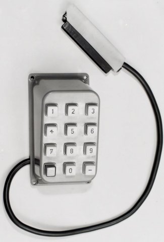 The SC Keysender No. 1 comprises the Key Unit
No. 4/1A
(show pictured to the right) and the Sender Unit No. 9B-1.
The SC Keysender No. 1 comprises the Key Unit
No. 4/1A
(show pictured to the right) and the Sender Unit No. 9B-1.