LORIMER SYSTEM
| |||||||
| The information below is taken from the book "Modern
Electrical Engineering - Volume VI". The date of publication is
unknown.
Taken from
Fig. 66. - Lorimer Wall Telephone with Levers set to call No. 9641 (shown to the right) Fig. 67. - Lorimer Table Telephone with Calling Mechanism removed from Cover Fig. 68. - Lorimer Calling Mechanism (two curved number stripes removed) The levers and numbers are not affected by the connecting up and have no normal position, remaining wherever placed by the subscriber, so that if the wrong number is obtained a check with the number in the directory of the subscriber wanted will at once show where the trouble has arisen. The exchange switching apparatus is operated by coupling it to a constantly moving shaft shown in figs. 70 and 71. The movements of the switches are therefore uniform, and not under the control of any variable signalling apparatus at the subscriber's end; as already explained, the switches control the movement of the subscriber's calling device. This shaft is now the only continuously moving portion of the apparatus, as the decimal indicator has been superseded by line and cut-off relays. Fig. 69. - Lorimer Wall Telephone, showing Right-hand View of Calling Mechanism Fig. 70 - 100 Line Switching Unit, with Seven Connective Divisions or Cord Circuits The line of the calling subscriber is searched after and found by the wipers of the A or line-finder switch of the connective division which is attending to the call. The calling line does not directly find a disengaged switching apparatus, but a disengaged switching apparatus is brought into action to find the calling line. Fig. 71. - Main Shaft and Drive Wheel Fig. 72 - Circuits Involved in Calling a Line The private and line banks are not separated, but fitted in adjacent positions in the same cylinder, as shown at AL 1, AL 2, AL 3 in fig. 72. These cylinders also contain signal and battery feed tags. An individual wiper is provided for each level of contacts. There is not combined "up and around" movement as in other systems, such as the Strowger. In the A, B, and inter-connector switches there are actually four wipers per row spaced out horizontally 90 degrees apart. Some of the wipers in the various switches are paired vertically, others horizontally, but in whatever combination they may be arranged, or however spaced, the wipers in the same cylinder switch are each fitted to the common gearing of that switch and move together, making contact with the points in their own level as they pass along. The cylinder wipers rotate in one direction only, and pass from normal to active positions and return from active to their normal positions in a clock-wise direction, thus performing a complete revolution in a horizontal plane. Fig. 73 illustrates the principle of the cylinder and register switches, which form a complete A or B connector switch, and also may be used to represent the inter-connector switch. The hundred circuits are distributed over the four quadrants as shown. The ten cylinder wipers are fixed to the common gearing s, and are individually connected by means of conductors a, b, c, d, e, f g, h, j, and k to the register bank contacts. The register wiper is on its own gearing, and moves independently of the cylinder wipers. Fig. 73. - Principle of Cylinder and Register Switches To connect calling-line A to No. 89, the register wiper is moved to its bank contact 80, and the cylinder gearing S is independently rotated until the ten wipers are on the cylinder contact points having 9 as their units digit; A is thus connected via 80, j and No. 80 cylinder wiper to 89. A similar action is performed if 89 is the calling line which has to be found by the wipers and connected through to the junction line A. It will thus be seen that a vertical movement is not necessary with such an arrangement. The actual construction of the combined cylinder and register switches is shown in figs. 79 to 84. Figs. 74 to 78. - Views of Cylinder Switches A time-limiting device is provided, which can be adjusted to limit conversations to a definite length, at the expiration of which, if not already completed and cleared, the connection will be broken automatically, and a fresh call will be necessary to continue the conversation. The extent of the time limit can be varied by re-arranging the gearing. This device is also brought into operation if a connective division is faulty and does not take up a call. It is also of service in preventing one subscriber holding up another by failing to restore his receiver. Figs. 79 to 84 - Views of the cylinder switches The advocates of the Lorimer system claim the following points in its favour:-
Stated in general terms, the Lorimer system in its
present stage of development, as fitted for the British Post Office, is as
follows:- The subscriber's set is illustrated in figs. 66, 67, 68, and 69. Fixed to each lever and moving with it is a curved strip having figures 0 to 9. The levers are in their right position when the required numbers are visible at each window. Fig. 87. - Supervisory and Timer Fig. 97 shows the normal position of apparatus ready to receive a call. The levers as shown are set with their earthed springs on contact-pins 1, 7, 4, and 6 respectively. When the crank handle is turned the brush arm is mechanically shifted, so that its brush rests upon contact E. The arm c is lifted out of the notch and rides on the ridge of the disc, consequently the arm extension d presses spring a into contact with b. The turning of the crank handle also winds up a spring which tends to rotate the toothed wheel carrying the disc and brush arm in the direction shown by the arrow. Fig. 98 is the theoretical circuit when a call has been "turned in". Impulses from the exchange signal controller switch pass over line 2 via b and a through the signal or stepping magnet, as in fig. 97. The movement of the armature and the corresponding operation of the double-toothed pawl allows the toothed disc to rotate under the tension of the spring, and the brush which is connected to line 1 is carried over the points. At the exchange end of line i is a relay which is operated immediately the brush touches an earthed contact. As will be shown later, during the interval between the time of touching the first contact of each quadrant and the time when the earthed contacts are reached, three register magnets at the exchange record the number of levers passed over, and register the numbers set up in the thousands, hundreds, and tens quadrants respectively. The impulses over line 2 during the passage of the brush over the fourth or units quadrant cause the operation of the wipers of the final switch to move and pick up the called line. Fig. 88. - A or Line-finder Switch Fig. 89. - Pilot Switch and Ringing Register
The subscriber's speaking circuit consists of a combination of two non-inductive resistances and two bridging coils, with the receiver in bridge. Elevation and general views of the apparatus are shown in figs. 70 and 71. The drive motors are of 1 horse-power each. One motor is sufficient to drive twelve switch-boards, each having seven consecutive divisions. The power is transmitted by belt to the main shaft, which is carried at right angles to each switching unit, as in fig. 71, and by means of gearing keeps in continuous rotation, at a uniform speed, the horizontal main shaft of each switch-board, which in turn is geared to eight vertical shafts, as in fig. 79. Clutches are provided to release any defective part from the driving-shaft, thus preventing accident to one part from affecting the operation of the other parts. The moving parts of the switches, i.e. the wipers, are driven by machine power transmitted by the vertical shafts, and the distance and times of their movement are under magnetic control by means of a loose gearing, as will be explained. The construction of all the cylinder switches, A, B, signal controller, interconnector, pilot and division starter, is similar. External and sectional views of these cylinder switches are given in figs. 74 to 84. Fig. 90. - Timer and Commutator Circuits Fig. 92. - Interconnector Switch and Hundreds register Fig. 93. - B or Final Switch and Tens Register The tags, 60, are first fixed in position in a made-up metal mould. A mixture of plaster of Paris and water is then poured into it, and, as the cement solidifies, the tags become embedded in the mixture. The whole is placed in an oven and baked, after which the metal mould is taken to pieces and removed. The plaster of Paris cylinder with its tags is then immersed in a mixture of paraffin and Brazilian wax, raised to a temperature above that of the boiling-point of water, but below that of boiling paraffin; it is then removed and allowed to cool. The Brazilian wax prevents absorption of moisture, and counteracts the hygroscopic nature of the paraffin. The cylinder is finally varnished with shellac. The tags and wipers are of German silver. The wipers, which consist of two flat springs and make contact with both faces of the tag contacts, are fitted in a cast-iron spider and insulated by means of India-rubber. The speed of the cylinder wipers is 24 revolutions per minute, with the exception of those of the B switch, which make 12 revolutions per minute. An examination of figs. 74, 75, 76, 78, 79, 82, and 83
reveals the following: When the clutch magnet 14 is energized, 83 is pulled
out of its notch into the position shown in fig. 79; the armature elbow 84
presses its roller against the pivoted frame 77 and causes 76 to engage with
the continuously rotating toothed disc 74. The motion is therefore
communicated by 76, 78, idler wheel, 79, and 80 to 72. 72 and 82 rotate. 72
is geared to 63, which is primed to the spider 70, shown in figs. 76 and 78.
The wipers move accordingly. It should be noted that 63 also carries plate 92, on which the register mechanism is mounted. The register moves as a whole with 63; the relative positions of its wipers and contacts are unaffected at this stage. The chamfered edges of the teeth of disc 23 assist 83 in rising clear of the notch should the impulse through the clutch magnet be brief, and so long as 83 rides on the ridge of 23 the rotation of 63 and 23 must continue. Thus the stop positions of the wipers and the number of contact points passed over depend upon the positions of the notches in 23; these positions are varied with each switch, as will be seen by comparing the notched discs in figs. 72 and 88 to 96. The adjustable antagonistic spring 73, shown in figs. 79 and 80, causes the restoration of 83 to its normal position immediately a notch comes within range after the clutch magnet is de-energized. Plan views of the register are given in figs. 82, 83, and 74, and these, when considered together, explain the actions of the register, which is mounted on 92. Fig. 83 shows the wipers in their normal position, with the spring 88 in tension. The spring has a flexible strap which passes round B, and is fixed to a pin in the sector 87, close to 86. When an impulse passes through the register magnet 28 the armature extension strikes the arm 90 of the scape lever 89. Escapement sector 87 therefore shifts its position in the direction of the arrow in fig. 83, and moves the wiper 61 to the next contact point. After five such impulses the wipers will be in the position as shown in fig. 74. Ten impulses cause the brush to assume the position shown in fig. 82, and this is as far as the wipers may move, being stopped at this point by mechanical means. Fig. 94. - Relay Call Indicator To understand how the combination is brought into its normal position, as in fig. 83, it is necessary to explain that A in fig. 82 is the pivotal centre of the plate 92, which carries the sector, and that the pivotal centre B of the sector itself is eccentric to A, consequently when the release of the cylinder switch takes place the plate 92 moves round with it, and if the wipers are off their normal position, 93 will be at such an angle that it strikes against 94, rigidly fixed to the permanent framework. The toothed sector 87, with its wipers, therefore remains stationary, whilst the register contact frame E rotates with 92, and its contacts move past the wipers. When E reaches the position as shown in fig. 83 the normal tags have been brought into contact with the wipers, the eccentric action has shifted 93 clear of 94, spring 88 has been put once more in tension, and the scape lever and pallet 89 and 90 have been carried along with the mounting plate 92 to the end of 87. The combined cylinder and register switch can be swung out for examination as indicated in fig. 78. The decimal controller shown in fig. 72 diagrammatically as a bar, half of which is split up into small segments, is actually a commutator ring, and the brushes are placed at opposite points on its diameter, as shown in figs. 85 and 86. Its action is very simple. When the clutch magnet is energized, the toothed wheel 180 rotates, and carries the two brushes with it around the commutator. The solid half is the collector segment, to which the brushes connect the small segments in succession. The Lorimer system is essentially a wiring scheme, and a full description of the many circuits cannot be given, but in order to give as clear an indication as possible of the actual working, the operations involved in setting up a call between two subscribers may be indicated. Fig. 97. - Ordinary Subscribers' Telephone Circuit Assuming that line No. 1714 sets up a call (fig. 97), then its line relay on the 1-700 group operates, and with it the sequence relay 04, as shown in fig. 72. The No. 4 units and the No. 1 tens identifying wires are earthed, thus signifying that a line having 4 as its "units" digit and 1 as its "tens" is calling. The sequence relay starts the division starter hunting for an idle connective division, and when one is found the pilot switch is energized, and this brings in the A switch to find the calling line. Simultaneously with this action the decimal controller is operated; its brushes move forward, and on reaching the earthed tens identifying wire are, in turn, earthed by the operation of the decimal relay. These brushes, passing on, cause two positive impulses to be sent over D 11 wire to the tens register, electrically informing it that the tens digit of the calling line is 1. The register wipers D move forward to the second tens contacts C. The pilot switch also operates the line-finder clutch magnet and keeps it energized until all the cylinder wipers reach the No. 4 units tags, when the circuit of the feed relay i is closed by finding earth on the No. 4 units identifying wire, and so breaks the line-finder clutch-magnet circuit. The calling line is now through, via A, B, C, D, E, and F to the pilot switch, and the division starter and decimal controller are free to attend to another call. The calling line is also guarded against other calls. The time taken to find the calling line is 1.25 seconds. The pilot switch next brings the signal controller switch into action to ascertain the numbers set up at the calling telephone and to adjust the ringing and interconnector registers, as in fig. 98. During the passage of the wipers over the first half of the signal controller cylinder impulses are sent over line 2 of the subscriber's circuit, and these operate his mechanism. While the impulses are passing, feed relay I tests the second wire, which is connected to the subscriber's moving brush, and the ringing register records the number of impulses sent out before the position of the thousands lever is found by the brush. The ringing register thus joins up the particular ringing commutator for ringing up the called subscriber. The interconnector register is next brought into circuit. The signal controller and test relay repeat their former operation as the wipers pass over the second half of the controller cylinder, and the interconnector register records the number of impulses sent out before the position of the hundreds lever is found. The wipers of the interconnector switch proceed to hunt for a junction line to this hundred group, as in fig. 99. If the wanted line is in the same hundred group as the calling subscriber, the interconnector wipers may pick up any idle B switch in its own group, but not necessarily the one in its own vertical division, which may have already been engaged by some other caller. Fig. 98 - Signalling Circuit Arrangements Fig. 99 - Interconnector Search for a Disengaged B Switch Fig. 100 - Busy Testy and Guard Circuit When an idle B switch of the particular group is found, a signal is given to the pilot switch, which moves to position 4, and in turn signals the signal controller to pass to its normal position, which, when reached, causes a further impulse to the pilot, whose wipers are then moved to position No. 5. The signal controller and test relay repeat their previous operations in order to ascertain the tens and units digits set up, and the wipers of the B switch come to rest on the called line, as in fig. 100. The signal controller pauses while the pilot moves from position 5 to 6 and makes the busy test. The signal controller is then signalled by the busy-test relay, and resumes its normal position, completing its operations by signalling the pilot to move to position 7, where the pilot makes a momentary pause before moving to the first ringing position, to ensure that no distorted ringing signal shall go out to the called line. After one code ring it moves to position 9, where, if the caller's receiver is off, showing that it is a proper call, it moves to the second ringing position, and rings until the called station replies. When the called station lifts his receiver the pilot switch moves to the talking position, operates the meter, and the calling line is now through. On the restoration of the receiver the pilot switch moves to its release position, and the various switches are brought to normal. The subscribers' lines are cleared immediately the pilot switch moves to the release position, so that a fresh call can be set up, and turned in, within one second of the restoration of the calling station's receiver. The circuit connections during conversation are shown in fig. 101. The thickened lines indicate the transmission circuit over which the speech currents pass. The Stone system of transmission is employed and the battery voltage is 32. Fig. 101 - Cord Circuit with Standard or Single Release Arrangements Relays 2 and 4 are the release relays prior to the talking position, when relay I becomes the release relay. The functions of relays 1, 3, and 4 are not wholly confined to speaking and release. Relay I is used as the test relay in conjunction with the signal controller switch during the registration of the numbers set up at the calling station. It is also used to test the units signal wires at the line-finder switch, and, when the calling wire is found, to break the circuit of the line-finder clutch magnet. Relay 3 is the talking feed relay on the B subscriber's side of the circuit, the test relay in conjunction with the interconnector when that switch is searching for an idle junction line, and also directly operates the meter of the calling line when the called subscriber replies. Relay 4 makes the busy test on the selected line in the B switch. The circuit, as shown, is arranged for the standard or single release. When the calling station restores the receiver to the hook, relay x de-energizes, R2 is earth, and the wipers are shifted to position 13, the position of automatic release and restoration. The wipers close the clutch circuits of the line-finder and final-connector switches. The line finder in turn causes the pilot switch to move to positions 14 and 15. The wipers in position 14 close the clutch-magnet circuits of the interconnector and signal controller switches. In position 15 the pilot switch wipers on level 14 close the pilot clutch-magnet circuit via J4, J2, and P39. Thus all the switches used in the connection are restored to normal, and each cylinder in its turn picks up its own register sector at its release point, and adjusts the register contacts and wipers to their normal position. The failure of the line-finder switch to restore would affect the restoration of the pilot switch, and, as a safeguard, a supervisory and timing device is brought into operation. This device is shown in figs. 87 and 90. As the brushes on level 8 pass from position I to position IX they bridge across the various contact points of level 8, closing the drive-magnet circuit via P52, N7, and the quick-drive commutator, which sends out impulses at the rate of 20 per minute, thus operating the drive magnet, whose armature pulls the disc round notch by notch. Should there be any abnormal delay in reaching position Ix, the disc will have been turned round so that the striker pin S presses a against c, thereby closing the circuit of the green supervisory lamp and alarm relay. At the next step the striker pin is further advanced, and pressure is also imparted by means of the coupled springs, c, b, to the two left-hand springs; a, b make contact, and if switch I be thrown over, the pilot-clutch circuit is closed via P 57. If the delay has been caused by other switches failing, the clutch operates and moves its brushes forward to position X. As the bridged brushes on level 3 pass from position IX to X they close the release magnet circuit via P 51, 21, 20, and earth. The operation of the magnet armature releases the detent, and the disc is pulled back to normal by the spring. During the daytime, when the attendant is on duty, the switches will be in the positions shown. The pilot release circuit P 57 would be disconnected. The attendant's attention is therefore directed to the failure, and he proceeds to investigate the cause of the trouble. Generally speaking, the release is only automatically effected when the attendant is off duty. If the brushes pass forward in their normal time they reach position X before the alarm can operate. The brushes on level 3 bridge contacts 20 and 21, and close the release-magnet circuit, and the disc is restored to normal, no alarm being given. There are various other methods of automatic telephone-working, but space will not permit of a detailed description of each of them. One of the most recent developments, it may be mentioned, however, is a system of automatic working by relays, without the use of the elaborate switching machines in use in the systems described, and which promises to give satisfactory results.
|
|||||||
Last revised: February 19, 2023FM2 |
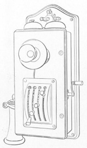 In this system, as already indicated, the call is set up,
first, by adjusting the levers provided on each telephone set (figs. 66, 67,
68, and 69); second, by turning the crank handle one revolution; and,
thirdly, by the subscriber lifting his receiver.
In this system, as already indicated, the call is set up,
first, by adjusting the levers provided on each telephone set (figs. 66, 67,
68, and 69); second, by turning the crank handle one revolution; and,
thirdly, by the subscriber lifting his receiver.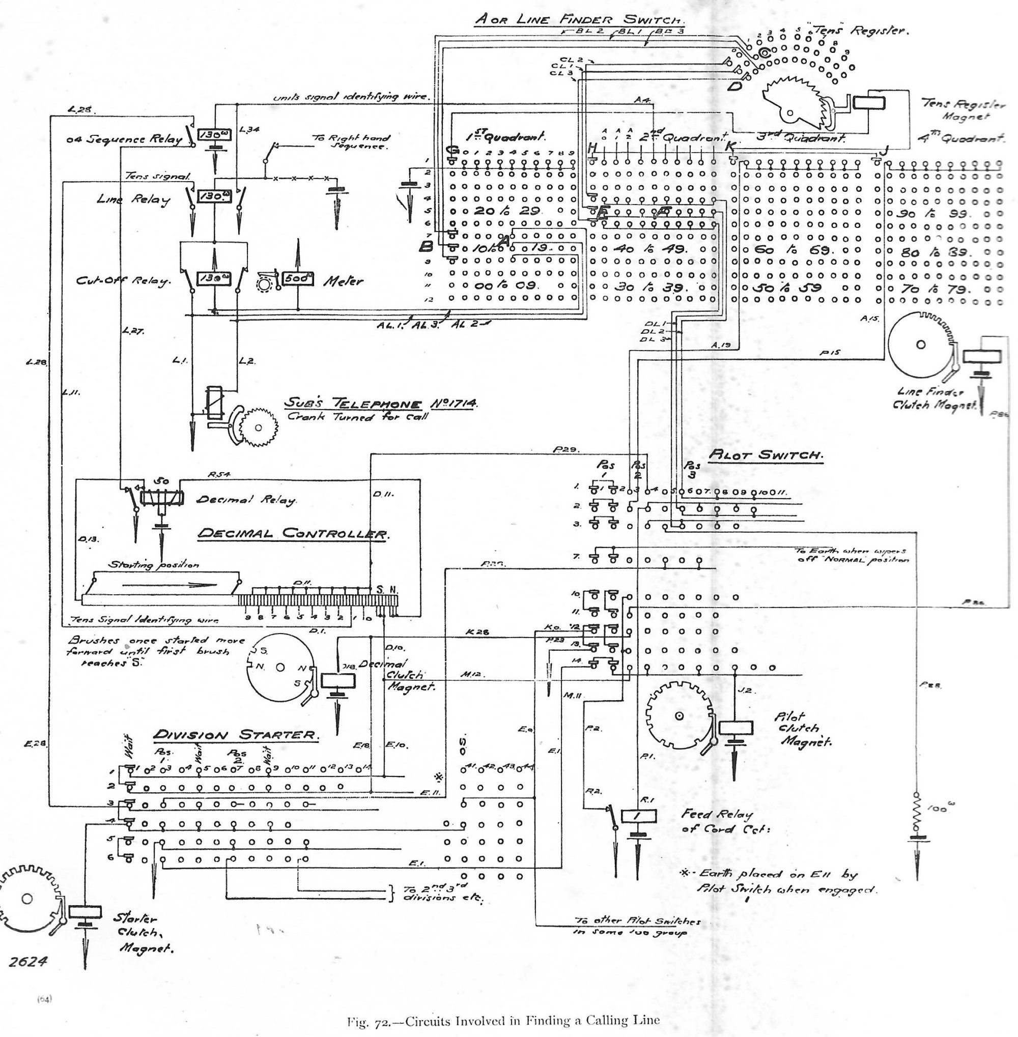