TELECOMMUNICATIONS INSTRUCTION
C MARKETING INSTALLATION
3 Internal
B2002
Issue 2, Oct 1973
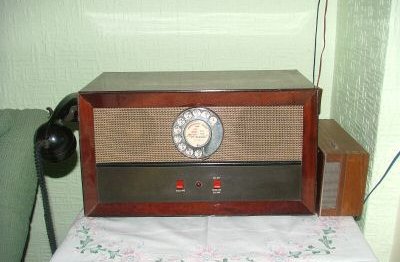
LOUDSPEAKING TELEPHONE No. 2
Installation
GENERAL
This
instruction gives details of the installation of Loudspeaking Telephone No. 2
(LST No. 2). Reference
should be made to B2000 for a general description of loudspeaking telephones, and for
information on the acoustic problems associated with loudspeaking telephone use.

DC POWER SUPPLY
The Loudspeaking Telephone No. 2 requires a d.c. supply of either 50, 26 or 6V nominal. The
total current consumption is 250ma at 50 or 26V, and is 80ma at 6v. The d.c. supply may
be provided by a power lead from the exchange battery, by a separate dry battery, or by a
Power Unit No 53A. The cheapest method of providing the power supply should be chosen for
each installation.
If dry cells are used, five Cells, Dry, R40 (in a Box, Battery, No. 6) should be provided,
and this should be noted on the exchange record card. At any subsequent maintenance visit
to the installation, the dry cells should be replaced automatically if they have been in
use more than nine months, and the date of renewal entered on the exchange record card.
Before using a power lead from an exchange battery, the daily voltage excursion between no
load and full load should be ascertained, and it should be verified that this variation
does not exceed the limits laid down.
At installations where there is not an existing exchange power lead, and where it is
undesirable to use dry cells, then a Power Unit No. 53A may be used.
LAYOUT
Agree with the subscriber a suitable position for the cabinet. It should be kept away from
radiators and, if possible, from direct sunlight to avoid the possibility of overheating
the equipment.
Determine a suitable position under a desk or on an adjacent wall to fix the external
junction box which is connected to the cabinet by an 8ft. length of multi-way cordage. Extend the exchange line leads and the d.c. supply leads to this position but do not
connect.
INSTALLATION
Diagram SA 4156 shows the circuit arrangement of the Loudspeaking Telephone No. 2 together with
the power-feeding connections. Installation should proceed as follows:-
-
The amplifying equipment is designed to work over a range of 5-7,8 volts. Three links, two
straps and a voltage control potentiometer are provided to achieve this voltage range with
different input voltage supplies. The three permissible nominal voltages are clearly
marked on the links as 50, 26 and 6v. The links are set initially for a nominal supply of
50V and require alteration for a nominal supply of 26 or 6v. Check that for a nominal
supply of 50, 26 or 6V the measured voltage of the supply does not exceed 62, 32 or 7.8v
respectively. Set the links, straps and voltage control potentiometer for the appropriate
nominal voltage as detailed in the notes on Diagram SA 4156, Sheet 2, and connect the power
supply to the set. It is important to ensure that the voltage control potentiometer is set
fully clockwise before the power supply is connected, as stipulated in the diagram notes.
-
After connection of the d.c. supply to the. set, the voltage control potentiometer
requires adjustment if a nominal 50 or 26V supply is used (the voltage control is rendered
inoperative when the links are set to the 6v position). Fig 1 shows the amplifier voltage
(VA) which should be obtained by appropriate adjustment of the voltage control
potentiometer. This graph applies only where the power supply is known to fluctuate
between the limits 38-59V or 18-29V. The voltage control adjustment is made as follows:-
Switch the set on and establish a connection without signal input from the line. In an
automatic exchange area this can be best arranged by dialling another number and holding
the connection in the 'called subscriber held' condition, thus ensuring quiet line
conditions. Measure the supply voltage (VS) across terminals J20 and J29 of the junction
box. Read off from Fig 1 the amplifier voltage (VA) corresponding to the voltage Vs just
measured. Turn the voltage control anti-clockwise until this value (VA) is measured across
terminals J15 and J29 of the junction box.
-
A Power Unit No. 53A may be used when it is undesirable to use dry cells because of
difficulty in periodical renewal or accommodation. A Power Unit No. 53A will provide
sufficient power for only one Loudspeaking Telephone No. 2. This power-unit gives a
12v d.c. output, and two additional resistors are required to reduce it to 6v. The two
resistors should be requisitioned as Resistor Coil 35-15 ohm and Resistor Coil 35A-39 ohm. Terminals J1, J4 and J8 are spare terminals in the junction box which can be used for
mounting the resistors. The Loudspeaking Telephone No. 2 is then set up for the
6v
condition as previously described. Great care should be taken to ensure that the polarity
of the 12v d.c. supply is correct before it is connected to the junction box terminals.
TESTS
-
Make test calls , both local and junction, and check that the transmission performance
in both directions is satisfactory, using either the loudspeaking equipment or the
handset. These test calls should first be made to handsets at the distant end, and then,
if possible, further tests should be made to another Loudspeaking Telephone No. 2 to test
the performance when both instruments are switched to the loudspeaking condition.
-
Check the clarity of reception on each volume control position. There should not be
undue clipping of the first syllables of received speech, particularly on the first words
in sentences. The presence of room noise at one or both ends can affect the amount of
noticeable clipping, but with average room noise arising from other conversations within
the room, closing of doors and moderate traffic noise, it should still be possible for
each end to interrupt conversation from the other end. If there is excessive speech
clipping, or if the voice switching is otherwise unsatisfactory, then the receive
amplifier may be readjusted as described in par 6, if the requisite testing apparatus is
available.
-
Check that the indicator lamp glows when the ON key is operated.
ADJUSTMENTS
The receive amplifier gain control (RV2, Diagram SA 4156) may be adjusted to suit local
conditions, or the subscriber's requirements. Adjustment should be made with the INCREASE
VOLUME key on the front panel in the normal position. RV2 is mounted on the chassis of the
loudspeaking telephone. Other than this the receive amplifier does not normally require
adjustment. If however, the receive amplifier is to be readjusted because of excessive
clipping of received speech, arrange the test circuit as shown in Fig 3 and then proceed
as follows:-
-
Connect a d.c. supply to the loudspeaking telephone as described in paragraph 4.
-
Disconnect the microphone lead from the microphone potentiometer. This potentiometer
consists of four carbon resistors mounted on an insulating board mounted vertically on the
top of the chassis adjacent to the calling buzzer.
-
Set potentiometer RV2 fully anti-clockwise, i.e. for maximum receive volume.
-
Set the Attenuator No 5 for maximum attenuation and set the Oscillator No. 29A to give
an output of 0dB at 800 c/s.
-
Adjust the Attenuator No 5 to give a voltage of 8.2v d.c. across capacitor C12 (Diagram SA
4156) when measured by a Meter, Multi-range, No 12 or other instrument of equivalent
sensitivity (20000 ohms per volt). Drawing CD 1652 shows the position of C12 on the amplifier
label.
-
Adjust RV1 (Diagram SA 4156) to give a level reading of -5 dB on the Tester RP790.
-
On completion of the tests, RV2 may be readjusted to suit local conditions.
PERFORMANCE
In common with all loudspeaking telephones the performance of Loudspeaking Telephone No. 2
is dependent upon the local acoustic conditions and upon the line attenuation. Under
extreme conditions it will be necessary to use the associated handset to make a successful
call. For further information on this aspect reference should be made to B2000.
Formerly EI Telephones, Stations, F3003
ADDITIONAL INFORMATION
Originally called the Telephone No. 1000L (GEC Paxmaster 660592) and introduced in October
1959. The description was changed to LST No. 2 in February 1960.
This Telephone was produced by GEC.
There was also an "LST No. 2 Old Gold" and on this model the whole of the
case, front rings, bezels, rubber feet, key handle and lamp cap were
finished in Old Gold.
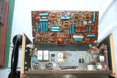
LST No. 2B is similar to LST No. 2A except that the Handset No. 1 has been replaced by a
Handset No. 3 and the rear amplifier panel has an improved mounting arrangement.
Diagram SA 4156_1 - LST 2
Diagram SA 4156_2 - LST 2
Diagram SA 4161 - LST 2A
Diagram SA 4175 - LST 2B
Drawing - 10087.
Specification - S608.
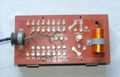
Wiring Instructions
(taken from diagram SA4156)
Please refer to the picture above, which shows the external junction box:-
The following terminals are linked in the external terminal block:-
- 23 and 24
- 25 and 28
- 26 and 27
Line connections:-
- A leg to terminal 27
- B leg to terminal 28
For a nominal 50v supply:-
- Set voltage control fully clockwise (the knob to the left of the
capacitor).
- Set all three links to the 50v position.
- In the loudspeaking telephone ensure that there are no straps
or links between terminals 26, 27 and 28.
- Connect the 50v + to terminal 29 on the external terminal block.
- Connect the 50v - to terminal 32 on the external terminal block.
- Adjust the voltage control as per the Telecommunication Instructions
above.
For a nominal 6v supply:-
- Voltage control is inoperative.
- Set all three links to the 6v position.
- In the loudspeaking telephone ensure that terminals 26, 27
and 28 are linked together.
- Connect the 6v + to terminal 29 on the external terminal block.
- Connect the 6v - to terminal 31 on the external terminal block.
|