|
Mechanism No. 14 is an A&B (prepayment) mechanism that superseded the
Mechanism No. 13.
The main difference being the way the mechanism connected to the main
casing. In this case the large bullet
shaped brass connectors of the No. 13 have been replaced by a small
connector plug (shown lower right), consisting of U type springs.
The U type springs are numbered from the bottom upwards.
The Mechanism No. 14D was introduced when
the UK converted to decimal currency.
Early mechanisms had an "A" embossed in the face of the A
button and the B button sometimes had the letter "B" embossed in the facing
side.
The Mechanism No. 18 was
introduced in certain areas, specifically modified to deal with American and
Canadian one cent coins.
In October 1951 these mechanisms were modified when the
unit charge was raised to 3d.
Diagram - N1167
(Mechanism wiring).
Diagram - N1185 (Parts listing).
Specification - S260.
E.I.
Telephones, Call Offices D5501 - Spare parts available to CCB
Maintenance Centre Staff and other Maintenance Staff.
E.I. Telephones, Call
Offices D5502 - Spare parts available to CCB Maintenance Centre Staff
only.
E.I. Telephones, Call Offices D5001 - Maintenance adjustments.
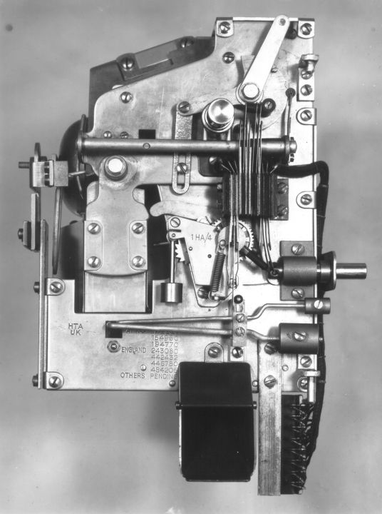 |
Front view of the mechanism
The smaller connector plate is the the lower right
Only the wiring side is showing |
| |
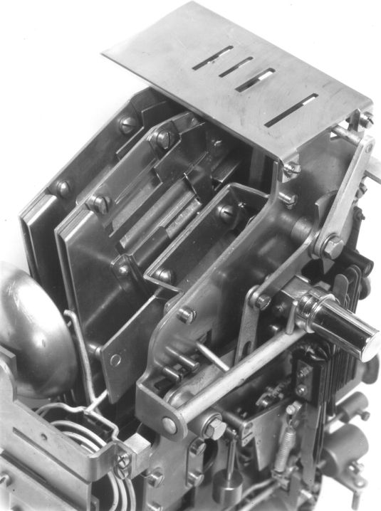 |
Top view showing the coin runways.
The bell is a transmitter and the gong would sound when
shillings were inserted.
The transmitter would indicate when copper coins were inserted
and the operator would hear the sound injected onto the line,
whilst the audible sound of the gong would be heard via the mouthpiece of the
telephone. |
| |
 |
| Mechanism No.14 with parts named |
Operation
The following circuit diagrams and the
picture shown above should be
referred to in conjunction with the operating instructions below:-
The mechanism is a pre-payment type, where coins must be inserted before
dialling commence. The call is controlled completely by the caller and
on answer the A button is pressed. On no answer the B button is
pressed to get the coins refunded.
COIN SLOTS
Three coin slots
marked Penny, Sixpence and Shilling respectively are provided en the top of the
box. The size of each slot is
such as to prevent the use of coins of a larger size than that of the denomination
shown or badly bent or misshapen coins.
COIN GUIDES
Each
coin
inserted rolls down an inclined coin guide associated with the
respective coin slot. In doing so the coin is tilted and caused to
pass over a suitable coin gauge.
COIN GAUGES
If a smaller coin than that indicated has
been inserted, it is thrown out by means of the coin gauge and falls into the
refund chute to
be returned to the caller.
COIN SLOT CRANK ARM
The first coin inserted
engages the can slot crank arm which operates spring assembly number 1.
BELL GONGS
At the end of the coin guides is fixed the gong assembly. Each
coin after passing its respective coin gauge,
continues to roll down the coin guide and is therefore caused to strike
either the wire or bell gong
in the fallowing manner. A penny strikes the bell gong once; a sixpence
strikes the bottom edge of the bell gong once; a shilling strikes the bell
gong twice i.e. by means of a double coin guide a shilling is caused to
strike both the top and bottom edges
of the bell gong.
BALANCE ARM
Each coin, after striking the gong,
falls down the swinging container and comes to rest on the balance arm.
The operation of the balance arm causes spring assembly number 2 to be
operated. The balance arm is restored to normal when coins are
deposited or refunded. The restoration of the balance arm restores
spring assembly number 2.
COIN BOX TRANSMITTER
The
coin box
transmitter is fixed inside the bell gong, the combined item being known as
a Transmitter No. 21 or 25 (later type). The coin box transmitter is
practically unresponsive to speech but responds to the
mechanical vibrations of the gongs.
A BUTTON AND A BUTTON LEVER
The A button operates the
A button lever which causes the swinging container to swing over the deposit
chute (and so deposit any coins previously held in suspension on the balance
arm) and
also restores the coin slot crank arm and spring assembly number 1.
B BUTTON AND B BUTTON LEVER
The
B button operates the B button lever which causes the swinging container to
swing over the refund chute (and so refund any coins previously held in suspension on
the balance arm)
and also restores the coin slot crank arm and spring assembly number 1 and
operates the escapement mechanism.
ESCAPEMENT MECHANISM
The escapement mechanism operates spring assembly
number 3. The escapement is adjusted to function for about 7 seconds.
Spring assembly number 3 remains operated during
the period the escapement is functioning and then restores.
|