OVERHEAD CONSTRUCTION
| |||||||||||||||||||||||||||||||||
|
Click here for Overhead Construction Menu Multicore underground cable was introduced early on in Telecommunications but aerial cable was not used that much. This was probably due to the cost of producing small quantities and the technology involved in hanging such a cable. The obvious way to hang a cable in those days was the catenary wire, where a steel wire is suspended, between two points and a cable attached to it. The GPO used this idea and attached the cable by various forms including the use of a lashing machine which wrapped a wires around both the catenary wire and the multicore cable. In the 1950's the catenary wire became integral to the multicore cable and self suspended aerial cable was thus formed. Erection of aerial cable was more difficult than small gauge open wires and specialist equipment was designed to assist. This cable was generally used in rural areas where undergrounding cables was expensive or impossible. PO ENGINEERING INSTRUCTIONS AERIAL CABLING 1. General For information on construction practices when using this type of cable see F 3191. In view of the large quantities existing in the field, information on superseded-fittings is given in paragraph 7. 2 Cable, Aerial, Self-supporting, Combined The sheath is polythene and the cable core is equivalent to that of Cable, Polythene, Twin, as described in Underground, F 1058. Details of cable size, maximum external diameter of the core, and total weight per yard, are given in the Vocabulary of Stores. (NOTE:- Except for a limited trial quantity, aluminium
conductors will not be used in aerial cable for the present.) 4. Suspension Strands During manufacture, the suspension strand is laid up parallel to the core and the whole is then enclosed within a black polythene sheath to give a figure of eight cross section - see Fig. 1. 5. Conditions of use If the cable is used in the vicinity of power circuits, the requirements shown in Protection, Power, D 0016, D 0018, D 0019, D 0020, E 0011 and E 0020, must be observed. If used at railway crossings see F 3135. Aerial cable with integral suspension strand should not be used
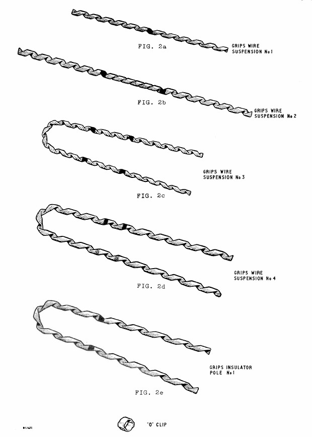
for the replacement of odd lengths of other types of aerial cable, because of
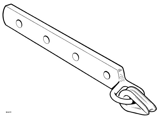
the differing tension requirements. Grips, Wire, Suspension Grips, Wire, Suspension No. 1 are used to terminate 1/12 suspension strand and Grips, Wire, Suspension No. 2 are used to terminate 7/26 suspension strand. If it is required to fit an Insulator, No. 2 in the suspension strand, a Grips, Wire Suspension No. 3 is used to secure a 1/12 strand to the insulator and a Grips, Wire Suspension No. 4 is used to secure a 7/16 strand to the insulator. The insulator is secured to the pole using a Grips, Insulator, Pole No. 1 with a suitable length of 7/14 suspension wire, for both 1/12 and 7/16 strands. Grips, Wire, Suspension, No. 1 and No. 2, Grips, Stay, Pole, No. 1 and Grips, Insulator, Pole No. 1, are supplied complete with "O" Clips. The "O" Clip is provided to prevent the free end of the suspension wire unwinding from out of the grip during the fitting operation or when the grip is subjected to high shock load. Hooks, Aerial Cable, No. 1 Plates, Wall No. 4 Plates, Wall, No. 5 Superseded Items
FIG. 1A
FIG. 1B
FIG. 2
FIG. 3
FIG. 4
FIG. 5
FIG. 6B
FIG. 6C
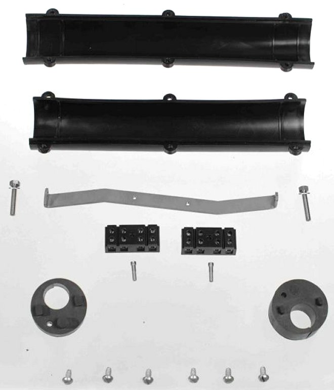
FIG. 6D PO ENGINEERING INSTRUCTIONS OVERHEAD DISTRIBUTION 1. General 2. Description The rubber end plugs are bolted, one to each end of a metal spacing bar, and are positioned between locating ridges on the inside surface of the sleeve sections. Each plug has a split hole for receiving the aerial cable to be intercepted and also two small holes which will accommodate all sizes of dropwire. In the case of Couplings, Aerial, Cable, No. 1, the plugs have an additional hole through which a small polythene spur cable may enter the joint. There is a thin membrane of rubber on the inside end of each plug which has the effect of reducing the size of all the holes and provides a partial water barrier. The rubber plugs are supplied complete with ebonite stops which seal the unoccupied holes when the coupling is fitted. The metal spacing bar is also used as a mounting plate for Connectors, Dropwire (see F 1051), using Screws, 6BA X 2in.Csk. Hd. Br.Ni..P. The connectors are fitted as required without a cover and are used for the following purposes:-
NOTE:- Connectors, Dropwire and the fixing screw are not supplied with Couplings, Aerial, Cable - additional requisitions are required.
FIG. 1 3. Sizes
NOTE:- Each of the rubber end plugs supplied with Couplings, Aerial, Cable No. 2 will accommodate two dropwires. Exceptionally, all four of the dropwire entry holes can be used. In such cases however, it is necessary to secure the back ends of the intercepted cable pairs to the main core of the cable and the coupling must be replaced by a Couplings, Aerial, Cable, No. 1 as soon as possible.
FIG. 2 4. Conditions of use
The couplings must not be used for other types of joint, e.g. joints between adjacent lengths of cable, joints between aerial and underground cable. If it is required to intercept pairs at the first pole on an aerial route, the pairs should be extended from the joint with the underground cable and terminated on a block terminal.
COUPLINGS, AERIAL, CABLE, No. 1 PO ENGINEERING INSTRUCTIONS OVERHEAD DISTRIBUTION 1. General For details of constructional features and conditions of use of the couplings see F 1053. For list of tools required see TOOLS & TRANSPORT, General, A 0040. 2. Safety 3. Preliminary work If Connectors, Dropwire, are to be used, fit these to the spacing bar inside the coupling before climbing the pole - ensure that the rubber end plugs are bolted to the spacing bar with the rubber membrane on the inside. Prepare Strips, Binding using Shears, Hand, Tinman's, 10in; three lengths each 17½in. long are required for Couplings, Aerial, Cable, No. 1 and two lengths each 16 in. long for Couplings, Aerial, Cable, No. 2. 4. Position of the coupling 5. Preparation for jointing Remove the cable sheath where the coupling is to be fitted, using Strippers, Cable, Sheath, No. 3 and Knife, Pocket, No. 2. Take care not to damage the conductors. Remove 7½in. of sheath if fitting Couplings, Aerial, Cable, No. 1 and 4¼in. if fitting Couplings, Aerial, Cable, No. 2. Trim the surplus web material remaining on the sheath in order to ensure a good circular fit at the entry hole. Using the slit entry hole, position the rubber end plugs and spacing bar on the cable. Take any dropwires through the small stepped holes, the first two dropwires entering the coupling from the pole side. Spur cable is taken through the subsidiary cable hole from the pole side. It will be necessary to ease the dropwires and spur cable through the membrane on the rubber end plugs. The membrane must not be removed. NOTE:- If using the coupling on lashed polythene aerial cable, temporarily secure the lashing wire beyond the position of the coupling before releasing the lashing wire at the suspension clamp. 6. Jointing the cable conductors When connecting a spur cable to the main aerial cable, joint the pairs in accordance with Underground, F 3232. Waterproofed connexions are not required. Position the bank of sleeves above the spacing bar. (see Fig. 1).
FIG. 1 7. Connecting dropwires to cable pairs Couplings, Aerial, Cable, No. 1 (see Fig. 1) Number the Connectors, Dropwire, 1 - 8, commencing at the end remote from the pole, and proceed as indicated in Table 1:- TABLE 1
TABLE 2
8. Closing the coupling Close the coupling with the longer P.V.C. section placed uppermost between the cable and the suspension strand, making sure that the rubber end plugs are correctly positioned between the locating ridges on the inside surfaces of the P.V.C. sections. Temporarily fasten the two halves of the coupling together and then complete the closure by fitting Strips Binding, in the locating ridges on the outside surfaces of the sections, see Underground, A 3005. 9. Binding in (see Fig. 2) Using Tape, Plastic, Adhesive, 1/2in. Black, tape the dropwires and spur cable to the main aerial cable at 3in. and 6in. from the end of the coupling. For lashed cables, restore the lashing wire to the suspension clamp.
FIG. 2
|
|||||||||||||||||||||||||||||||||
Last revised: March 30, 2023FM2 | |||||||||||||||||||||||||||||||||