|
Click here for Overhead
Construction Menu
This was a game changer for connecting the overhead wiring to
the customers premises in the 1930's. Before the introduction of dropwire
the feed was open copper wires which terminated on a large two wire cable which
ran down the wall to into the building.
Dropwire, which is a two wire, insulated cable could be used
from the pole right into the building, as it was self supporting, lighter in
weight and smaller
than previous lead-in cables. It was a flat cable
and no joints in the cable were required as it was run in a continuous length.
This obviously cheapened the install as some of the time
consuming open wire to the premises was dispensed with. The parts were
also cheaper to produce and it
only consisted of a couple of component parts.
Dropwire was trailed at Golders Green in 1932. A
circular plate with pre-drilled holes, called the "Drop wire pole head", was
fitted to the top of the distribution poles. The plate had metal supports
that were bolted to the pole. Eccentric wheels were used as cable clamps
and these were bolted into the pre-drilled holes. The insulated twin wire
was called "Cable, rubber covered and braided for drop wiring, one pair, Cadmium
Copper Conductors" which is cleated from the "Block, Terminal" on the
distribution pole to the "Drop wire pole head".
Dropwire started life as a braided cable filled with compound.
The next step was a plastic covering which was more durable and lighter in
weight. Two types were produced called Dropwire No. 1 and No. 2. In
the 1960's the outer coating was made smaller and called Dropwire No. 3 and No.
4. As the cable got smaller and lighter a single man could install it and
an installation was then done by the "One Man Installer".
Originally the conductor wires were copper, but in the 1960's
steel conductors with a copper coating were introduced - Dropwire No. 3 and No.
4. Steel was good for self suspension purposes but one nick in the copper
coating on outside terminations caused a large fault issue, as corrosion can set
in rather rapidly. Dropwire No. 3 was replaced with Dropwire No. 6, which
was more robust with a thick covering.
The 1980's saw a new dropwire introduced. This superseded
all previous dropwire and was a self supporting, black,
round cable with 4 conductors This was
called Dropwire No. 10. Designed on similar lines, Dropwire Nos. 11, 12, 14 and
15 were produced.
The documents below are different, updated, versions of the same document
but they show the development of drop-wire distribution until the late 1980's.
P.O. ENGINEERING DEPT
ENGINEERING INSTRUCTIONS
LINES
OVERHEAD
C3101
Issue 4, 4.12.36
DROP-WIRE DISTRIBUTION
Description and use for subscribers' services
1. General
Covered drop-wire consists of two conductors of approximate weight 31lb. per
mile, each covered with a tough rubber insulation. The A-wire and B-wire are
laid up as a flat pair, and are enclosed in a robust cotton braiding impregnated
with a waterproofing compound. Special fittings, described in paras. 5 and 6,
are employed as supports at each end of the span.
2. The following types of covered drop-wire are available:-
-
Cable I.R.V. Braided and Compounded with black braiding,
for general use.
-
Cable I.R.V. Braided and Compounded with grey braiding for
use when the black type is likely to give rise to objections.
-
Cable I.R.V. P.B.J. for low-tension power crossings.
3. Advantages of Drop-wire
The use of drop-wire has the following advantages:-
-
Careful regulation, which is required to prevent contacts
between the conductors of a pair of bare wires, is unnecessary.
-
Additional drop-wires can be rim from the same pole without
risk of wire contacts.
-
Fault liability from contact with twigs and foliage is
reduced.
-
Drop-wire provides for a direct lead from the block terminal
to the subscriber's protector without intermediate connexions.
-
The running of drop-wire is generally more convenient, and
alterations to leading-in are more readily made.

FIG. 1. POLE SHOWING POLE-HEAD—RING TYPE WITH FINIAL
4. Restrictions on use in residential areas
Due to the greater visibility of drop-wire as compared with open-wire
distribution, complaints are sometimes made by public bodies or residents ; this
tends to increase the difficulty of obtaining subsequent consents. Discretion
should therefore be employed in its use. The circumstances which give rise to
the most serious complaints are:-
-
Across an open background of sea view or sky,
-
Across public gardens or ornamental grounds,
-
In localities with scenery of special interest or beauty,
-
Across main thoroughfares in towns,
-
In good-class residential districts where special attention
is being paid to amenities in the building layout.
5. Fittings for drop-wire distribution - Pole-heads
At the pole, distribution is effected by means of a pole-head, which consists of
a ring of channel steel secured to the pole by four brackets. The channel is
drilled to accommodate the spindles of "Clamps, Eccentric" (see Fig. 1). The
following classes of pole-head are available:-
| Size |
When used |
| 12 way |
a) Primarily for open-wire distribution with
"Spindles No. 7" (see G 3002). In certain circumstances may be used
for drop-wire distribution with packing pieces for Clamps,
Eccentric.
b) For mixed open-wire and drop-wire distribution. |
| 16 way |
For covered-wire distribution only; up to 16 pairs. |
| 16 way spilt |
For covered-wire distribution only; Used when the
ordinary 16-way pole-head cannot be fitted owing to existing arms. |
| 28 way * |
For covered-wire distribution only; above 16 pairs. |
* Under normal conditions a distribution pole with a greater
capacity than 15 pairs should be very exceptional, consequently the use of a 28
way fitting should be restricted to special cases.
6. Clamp, Eccentric
These contain a grooved mounted wheel, which grips the cable between the wheel
rim and the shoulder of the casting to which the wheel is fixed (see Fig. 2).
When correctly fitted, the action of the eccentric wheel ensures that the grip
on the cable is increased when the tension in the span becomes greater.

FIG. 2 - ECCENTRIC CLAMP WITH SPANNER
7. Fitting of pole for drop-wire distribution - Pole-heads
Except those of the split type, should be fitted so that the upper surface of
the ring is 6in. below the top of the pole. The wrought-iron fixing strips
should be adjusted, by bending, so that the ring is accurately centred on the
pole. Coach screws should be used for fixing.
8. Pole-heads of the split type should be fitted 6in. below the
lowest arm, when arms are to be retained on the pole.
9. Finials
A finial of the appropriate size should be fitted on D.P.s
used for service by drop-wire.
10. The terminal block should be fitted 8in. below the under
side of the channel ring, and should face squarely up or down the street.
11. An earth wire should be fitted in a direct line from the
finial to the ground, on the side of the pole opposite to the block terminal. It
should project 3in. above the top of the finial, and should be kept clear of the
iron work and cables.
12. Pole steps, four in number, should be fitted at right angles
to one another four feet below the level of the channel ring, for convenience in
working at the pole top. Additional steps for ascending the pole should be
fitted in accordance with C 3151.
13. Clamps, Eccentric are secured to the channel by spindle and
nut. The wheel of the clamp on the pole should be in direct line with the
corresponding wheel at the house attachment. This provision is most important,
since absence of alignment between the drop-wire and the wheel at either end of
the span, tends to result in damage to the braiding and insulation and is a
frequent cause of faults. The clamp should be turned so that the grip is
tightened by the pull of the drop-wire.

FIG. 3 - ILLUSTRATION OF THE METHOD OF TIGHTENING CLAMP
(Note: The clamp should be tightened by hand until it reaches this position.)
14. Wiring
The drop-wire should be run in one length, without joint or other connexion, to
its termination on the protector inside the building.
15. Spans should not exceed 60yds.
This limit is necessary to avoid excessive sag and undue strain.
16. The drop-wire should be led from the Block Terminal, through
"Screw eyes, Spiral, 1in." to the clamp, as shown in Fig. 1. A "Lead Sleeve No.
2A Split" should be placed round the drop-wire as a protection, at the point
where it passes over the wheel. The wheel should be tightened by turning it in a
clockwise direction, and the tightening should be completed with the aid of a
"Spanner, for Clamps, Eccentric" (see Figs. 2 and 3).
17. If the drop-wire runs in an upward direction on both sides
of the clamp, it may be necessary to invert the clamp so that the drop-wire may
bed properly on the wheel; special care must then be taken to ensure that the
wheel of the eccentric clamp is turned to the position in which the grip
increases with the pull.
18. In making the connexion to the block terminal, the two pins
of the spanner should be used to form loops at the ends of the wires (see Fig.
4).
19. When drop-wire is used for spurs on private property (see
para. 26 (b)) "Spindles No. 16" and "Insulators No. 2" should be used on the
pole for supporting the wire. Drop-wire should be bound to the insulator with
"Wire, Cadmium Copper, Insulated J."
20. Drop-wire damaged by excessive bending or kinking should be
scrapped. Ratchets should not be used to draw up the drop-wire; satisfactory
results are obtainable by hand regulation.
21. It is desirable that the runs used for drop-wire should
admit of its ready examination at points of attachment, also of the replacement
of a defective length without special difficulty. Runs on inaccessible roofs, or
in positions where the use of long ladders is required, should be avoided.

FIG. 4 - SPANNER FOR CLAMP, ECCENTRIC, SHOWING METHOD OF
BENDING WIRE
22. The direct connexion of drop-wire, to lead-covered cable is
inadmissible, but, in exceptional eases, where it is desired to replace open
wire by drop-wire without disturbing the existing leading-in cable, a connexion
between the drop-wire and the lead-covered cable may be made in an "Insulator
No. 16".
23. Drop-wire must be clear of tree branches and of any rubbing
contacts likely to damage the covering, it should not be used to avoid
tree-cutting (.see E 3150 and 5101).
24. Drop-wire across roads
At road crossings, in order to obviate any risks due to covered wire
working-loose at the eccentric clamp, the wire should be bound-in with "Wire,
Binding J" to the spiral eye nearest to the clamp at each end of the span (see
Fig. 5).

FIG. 5 - CORNER BRACKET
25. Leading off from open-wire line, and intermediate changes
from drop-wire to open wire
When a circuit consists in part of drop-wire and open wire, the junction should
be effected through "Insulators No. 16" with either "Spindles No. 10" or
terminal irons (see Figs. 6 and 7 for details).

FIG. 6 - COI FRED DROP-WIRE LEAD-IN FROM OPEN WIRES

FIG. 7 - TERMINATION OF OPEN-WIRE LINE AND DROP-WIRE
26. Use of drop-wire when the length of the spur from a branch
line is more than 60yds
The method to be followed will depend on local circumstances. Typical examples
and the appropriate practice are shown below:-
-
Spur exceeding 60yds. in length, but less than 120yds. -
Provide two spans of drop-wire
-
Spur of greater length than 120yds., on private property. -
Drop-wire may be provided throughout in 60yd. spans for all distances,
subject to the absence of objections on the score of amenities.
Alternatively, the span from the D.P. and the last span to the leading-in
may be drop-wire and the intervening spans open wire (see para. 25).
-
Spur exceeding 60yds. in length, along a public road. -
Drop-wire may be provided in 60yd. spans for one or two circuits. If more
than two circuits are required or anticipated, open wire or aerial cable
should be provided.
27. Leading-in
At the subscriber's premises, drop-wire should be run to a clamp fixed in either
a bracket or an insulator spike (see Figs. 5, 8 and 9). The drop-wire is secured
in the same way as at the pole-head, (see paras. 16 and 17). When it is desired
to use existing brackets or spikes that normally take a spindle greater in size
than the fin. spindle of the eccentric clamp, a good fit can be ensured by the
insertion of packing pieces for "Spikes, Insulator No. 1". Not more than two
drop-wires should be led to any house-bracket

FIG. 8 - INSULATOR SPIKE

FIG. 9 - BRACKET NO. 10A WITH CLAMP, ECCENTRIC, FITTED ON
FACIA BOARD AT SUBSCRIBER'S PREMISES.
28. "Spikes, Spiral Eye"
Two sizes are available, 3/8in. and 1/2in, The spikes are fixed at intervals of
about 18ins. for runs along walls. The in. size is suitable for supporting one
cable in normal brickwork, but, where the mortar course of the brickwork is soft
or there is a plaster coat, the in. size which has a longer shank will probably
be more suitable. The 1/2in. size will accommodate from 2 to 4 cables, (see Fig.
10). Screw eyes, spiral, in., at about 18in. intervals, should be used for runs
on wooden surfaces, such as facia boards, see Fig. 10.

FIG. 10 - SPIRAL EYE SPIKE
29. Suspension-strand method of erecting drop-wires
Special circumstances sometimes render it desirable to run a number of
drop-wires between two poles. When the number is greater than two, there is a
risk of the line becoming very unsightly if separately-run wires are used. The
suspension-strand method has been devised to overcome this difficulty. A 7/14
steel suspension strand should be run between the poles (see F 3126), and the
drop-wire threaded through "Rings, Cable No. 4", spaced on the suspension strand
at intervals of 20in., see, Fig. 11.

FIG. 11
30. The following are examples where this method can be usefully
employed:-
-
When it is required to feed not more than four circuits from
a drop-wire D.P. to an open-wire branch line.
-
When, due to wayleave difficulties, such as objections to
diagonal crossings over gardens, trees or other obstructions, it is
necessary to take off the lead to the subscriber's premises from an
intermediate point in the span (see Fig. 11). (At the point where the
drop-wire leaves the suspension strand, protection against chafing is
afforded by means of a split ebonite bush in the cable ring (see Fig. 12).

FIG. 12
31. Existing open-wire D.P.s
The building-up of mixed open wire and drop-wire D.P.s with arms should in
general be avoided, since this prevents the use of the less-obtrusive type of
D.P. proper to a drop-wire system, which is an advantage to offset the greater
visibility of the covered conductors. Where no objection on the score of
appearance is to be anticipated, however, drop-wire circuits may be added to
existing open-wire D.P.s. The eccentric clamp should be attached to the arm by a
"Bolt, Extension for Clamp, Eccentric" when a single circuit is required, or by
means of a "Bracket, Clamp, Eccentric 2-way" when two drop-wires are run from
the same arm (see Figs. 13 and 14).
 |
 |
FIG. 13 - BOLT EXTENSION, FOR
CLAMP, ECCENTRIC |
FIG. 14 - BRACKET, CLAMP,
ECCENTRIC, 2 WAY |
32. Power Crossings
When subscribers' wires, forming part of a drop-wire distribution system are
required to cross or approach closely to low-tension power lines or tramway
trolley wires, and the most economical method of providing the protection
demanded by TE 80 is the erection of insulated wires by the Post Office, "Cable
I.R.V., P.B.J." should be used.
P.O. ENGINEERING DEPT
ENGINEERING INSTRUCTIONS
LINES
OVERHEAD
C3101
Issue 6, 4.2.55
DROP-WIRE DISTRIBUTION
General
This Instruction relates to the use of-covered drop-wire for providing spurs to
subscriber's premises and describes the stores and methods to be used.
2. Conditions of use
Drop-wire is much more conspicuous than open wire and is liable to be considered
objectionable in residential areas or other places where amenities have to be
considered.. It is useful, however:-
-
where twigs and foliage cannot be avoided and the use of
open wires would therefore lead to an excessive number of-faults. In such
circumstances the foliage will often provide a background against which the
drop-wire will not be conspicuous.
-
on industrial sites or other situations where amenities are
not of particular importance.
-
as a temporary measure for the early restoration of
circuits, e.g. after severe storm damage, where the number of pairs involved
is insufficient to warrant the use of "Cable, Aerial".
3. Stores
The following items are available for use with drop-wire distribution:-
"Cable, I.R.V., Braided and Compounded, Black Braiding" -
for general use.
"Cable, I.R.V., Braided and Compounded, P.B.J. or "Cable, I.R.V., - for use
where protection from low-voltage or medium-voltage circuits is necessary.
"Clamps, Drop-wire" - for attaching drop-wire to poles and buildings
"Brackets No. 22" - for securing the clamps to buildings.
"Brackets No. 27" for attaching "Clamps, Drop-wire" to "Pole Heads, 15-way,
Ring Type, Split".
"Spikes, Spiral Eye" - for supporting drop-wires on masonry.
"Screw Eyes, Spiral" - for supporting drop-wires on woodwork, including
poles.
4 Description
"Cable, I.R.V., Braided and Compounded, Black Braiding" consists of two
cadmium-copper conductors each of 31lb. per mile and covered with a tough rubber
insulation; one conductor is red and the other black and they are laid up as a
flat pair within a strong, black, impregnated cotton braiding.
5. "Cable, I.R.V., Braided and Compounded, P.B.J."
This is similar to the cable described in para. 4 but has a red-coloured P.B.J.
covering. When stocks of this type of cable are used up, "Cable, I.R.V., P.C.P."
will be issued instead.
6. "Cable, I.R.V., P.C.P."
This cable consists of two cadmium-copper conductors, each of 31lb. per mile,
covered with black I.R.V. insulant and arranged in "double D" formation. The two
insulated conductors can be separated from each other by tearing the two
D-shaped sections apart. A cotton braid covers the I.R.V. insulant and the
whole is covered with an outer sheath of black Neoprene. Either conductor may be
identified by its position in relation to a rib on the outer sheath.
7. "Clamps, Drop-wire"
These are two piece, wedge-type clamps. The ring at one end is used to
secure it to fittings on poles and buildings (see Fig. 1).
8. "Bracket No. 22"
This consists of a small flat plate to which is welded a spiral eye (see Fig.
2).

FIG. 1 CLAMP, DROP-WIRE
9. "Spikes, Spiral Eye"
These are made in two sizes, the 3/8in. size for use in normal brickwork where
one drop-mire is to be supported and the 1/2in. size for use on plastered or
less solid walls or where up to four drop-wires are to be supported.
10. "Screw Eye, Spiral"
These consist of a spiral eye with a screwed shank. They are made in three sizes
1/2in., 3/4in. and 1in. and are used in woodwork to support drop-wires; in.
size for single drop-wires and the other sizes for larger quantities.

FIG. 2
10. "Brackets No. 27"
These are D-shaped brackets which can be fitted over the channel of the pole
head. The bracket is secured through the channel spindle-hole by a bolt provided
with each bracket.
12. Methods of distribution
The drop-wire for the subscriber's spur should be run in a continuous length
from the pole to the protector fitted inside the building. The length of the
spur should not normally exceed 60yds. The pole may be a ring-type D.P. a
subsidiary pole or, exceptionally, an arm-type and the methods to be adopted for
each type of pole should be as described in pars. 13 to 16. Drop-wire can also
be used for short spurs on private property, the wire in such cases being bound
to the upper groove of an "Insulator No. 3" with "Wire, Binding, J", the
insulators being supported on "Spindles No.16".
13. D.P.s
The fittings used and the method of attaching them should
be the same as described in E 3130 for open wire ring-type D.P.s, except that
the insulators will be replaced by "Clamps, Drop-wire" and the spindles by
"Brackets No. 27" to accommodate the clamps. The clamp is attached to the
drop-Wire as described in par. 17.
14. The drop-wire should be taken direct from the clamp to the
terminal block and supported on the pole by "Screw Eyes, Spiral".
15. Subsidiary Poles
The "Clamp, Drop-wire" should be attached to an existing spindle or, where this
is not practicable, to a "Bracket No. 22" or "Screw Eye, Spiral" fixed to an arm
or the pole at a Convenient position. Under-sized holes should be drilled in the
arm to take the screw eye or the screws for the bracket. The drop-wire should be
taken from the clamp to the spindle on which the open wires to the exchange are
terminated. The drop-wire should be connected to-the open wires, n the cavity of
an "Insulator No. 16". Any leads secured to the spindle to which the clamp is
attached should be so placed that there is no risk of-the clamp rubbing the lead
(see Fig. 3).
16. Arm-type D.P.s
The mixing of open and drop-wire from the same D.P. should not be regarded, as
normal but can be used where amenities are not of particular importance and then
only Where twigs, foliage or other obstruction prevent the use of. open wires.
The clamp should be attached as described in par. 15 except that the drop-wire
should be continued from the clamp to the terminal block, being secured to the
arms by "Clips, Pole Lead, No. 1" and supported on the pole by "Screw Eyes,
Spiral".

FIG. 3
17. Fitting the clamp to the drop-wire
The clamp should be held in one hand, with the ring towards the body. The
drop-wire should be laid along the flat surface of the inner member and held in
this position while the outer member, with the smaller end towards the ring, is
slipped over the wire and inner member. The assembled clamp should be fitted
with the serrated surface of the outer member underneath when the end of the
drop-wire is to be taken below the clamp. When the drop-wire is to be taken
above the clamp, the serrated surface of the outer member should be on top.
18. Removing the clamp
When it is necessary to remove the
drop-wire from the clamp, the larger end of the outer member should be struck
repeatedly with the flat surface of a suitable tool, e.g. the blade of a
screwdriver having a rectangular section blade.
19. It is important that the ring of the clamp should be free to
move on its support so that the clamp can move in a horizontal direction when
the drop-wire swings in the span.
20. Attaching the clamp to buildings
A "Bracket No. 22" should be used wherever possible. On woodwork it should be
fixed by four "Screws for Wood, Iron, Galvanized, Csk. Hd., No. 16" of suitable
length. On brickwork or other masonry the two horizontal or two vertical holes
should be used for fixing. The holes for the screws should be plugged as
described in E 3134.
21. Supporting drop-wires on buildings
On woodwork, the drop-wire should be Supported by "Screw Eyes, Spiral" and on
masonry by "Spikes, Spiral Eye". The supports should be equally spaced at
approximately 18in. intervals (see Fig. 2). Where the drop-wire is supported in
a spiral eye at a right-angled bend it should be protected with a lead sleeve or
scrap lead-sheath wrapped round the braiding at the point of contact.
22. Regulation
The tension for regulating the dip of-the cable should be applied by hand.. The
clamp at the building should be attached before the one at the pole. When
attaching the pole clamp, the drop-wire should first be pulled up to the
required tension and the position for the clamp noted. The clamp should then be
attached to the drop-wire, after which it should be secured to its bracket or
spindle.
P.O. ENGINEERING DEPT
ENGINEERING INSTRUCTIONS
LINES
OVERHEAD
C3101
Issue 8, 3.8.60
OVERHEAD DISTRIBUTION
Drop Wiring
1. General
This Instruction describes the types of cable arid associated fittings for
providing subscribers' drop-wiring spurs. The methods for providing open-wire
spurs are described in E 3125, E 3130 and E 3134.
2. Conditions of use
In general, subscriber's' spurs are provided more cheaply with drop-wiring than
with open wires, and drop-wiring should be provided wherever there is no strong
objection on grounds of appearance. Drop-wiring should also be used where
occasional contact with twigs or foliage cannot be avoided.
3. Types of cable available for drop-wiring
Two types are available:-
Cable, Drop-wiring No. 1 for spur's not involving a power crossing.
Cable, Drop-wiring No. 2 for crossing low or medium-voltage power wires.
4. Stores
The following items are available for use with drop-wire distribution:-
Cable, Drop-wiring, No. 1
Cable, Drop-wiring, No. 2
Clamps, Drop-wiring, No. 1
Clamps, Drop-wiring, No. 2
Rings, Pole-head, Drop-wiring
Brackets No. 22
Brackets No. 27
Hooks, Clamp, Drop-wiring
Screw-eyes, Spiral
5. Description
Cable, Drop-wiring, No. 1 (see Fig. 1) is a flat twin cable composed of 20lb.
cadmium-copper conductors with a solid P.V.C. insulant. The thin web of plastic
material shown in. Fig. 1 facilitates the separation of the insulated
conductors. For easy identification of the wires, one conductor is tinned..
6. Cable, Drop-wiring, No. 2 (see Fig. 1).
Is a flat twin cable composed of 31lb. cadmium copper conductors covered with
black V.I.R.
The cable is sheathed with cotton braid and black 'Neoprene'.
Either conductor may be identified by its position in relation to two
longitudinal ribs moulded on the sheath of the cable.

FIG. 1 - CABLE, DROPWIRING

FIG. 2 - RING, POLE-HEAD, DROP-WIRING
7. Ring, Pole-head, Drop-wiring (see Fig. 2)
Consists of two half rings of 1/2in. diameter mild steel with forged eyes at
each end. A 5/8in. bolt with two nuts is provided to secure a ring to a pole.

FIG. 3 - CLAMPS, DROP-WIRING
8. Clamp, Drop-wiring, No. 1 (see Fig. 3)
This is a two-piece wedge-type clamp of suitable dimension for gripping Cable,
Drop-wiring, No. 1. A ring is provided at one end for attaching the clamp to
poles and buildings. The clamp is also supplied with a shim or pressure plate to
ensure a good grip of the cable.
9. Clamp, Drop-wiring, No. 2 (see. Fig. 3)
Is similar to a Clamp, Drop-wiring, No. 1, but is only suitable for the larger
Cable, Drop-wiring, No. 2. The bottom of the wedge slide is serrated to ensure a
good grip of the cable and a pressure plate is not provided.
10. Bracket No. 22 (see Fig. 6)
Consists of a small square plate to which is welded a spiral eye. Four holes are
provided in the plate for securing the item by means of countersunk-headed wood
screws.

FIG. 4 - BRACKET No. 27 FITTED TO A RING-TYPE POLE-HEAD
11. Bracket No. 27 (see Fig. 4)
This is a small light shackle designed for attaching a Clamp, Drop-wiring to
Pole-heads, 15-way, Ring Type, Split (cast aluminium type).
12. Hook, Clamp, Drop-wire (see Fig. 2)
These consist of an open link of galvanized steel wire which can be readily
attached to a Ring, Pole-head, Drop-wiring, Bracket No. 22 or the shank of an
insulator. spindle (see par. 17) and provides a simple means of attaching
Clamps, Drop-wiring, Nos. 1 and 2.
13. Poles for ring-type D.P.s.
Except where a pole already exists, the pole used for a ring-type drop-wiring
D.P. should be a medium class non-precut pole. When an existing non-pre-cut pole
is used the top of the pole should be left fiat and not cut or modified in any
way. Finials should not be fitted except as detailed in C 3151.
14. Fitting the pole-head
The bolt securing the pole-head should be fitted so that the bolt-head and the
eyes of the ring will interfere as little as possible with the attachment of the
drop-wiring clamps. Least interference will usually occur if the line of the
fixing bolt is in the direction of the road. The pole-head should be fitted 9in.
from the top of the pole or in the top arm position on pre-cut poles and should
be secured to the pole by the 5/8in. bolt provided which is passed through the
eyes formed at each end of the two half rings.
A Washer, Galvd., No. 4 should be placed against the pole face
at each side of the pole and a Washer, Galvd., No. 17 should be used as a
spacing washer between the ring and the No. 4 washer on each side. There will be
considerable variation in pole diameters and so the length of the spacing
washers required will vary. If No. 17 washers are insufficient, one or two
Washers, Galvd., No. 13 may be used by inserting them between the No. 4 washer
and the No. 17 washer. If this is insufficient, Washers, Galvd., No. 16 should
be used and cut to the desired length. On pre-cut poles, more washers will be
required on the cut face of the pole to centralize the ring. The ring should not
be distorted when the bolt is secured. The first nut should be fully tightened
and locked with the second nut.
15. Fitting the terminal block at the pole
On drop-wiring D.P.s the terminal block should be fitted below the ring as shown
in Fig. 2. The terminal block may be fitted on either side of the pole directly
below the bolt-head or the nuts of the bolt securing the ring to the pole. The
centre of the top of the terminal block should be approximately 6in. below the
ring.
16. Drop-wiring leads on the pole
The drop-wiring on the pole between the terminal block and the Clamps,
Drop-wiring should be run in Screw-eyes, Spiral screwed into the pole in the
positions shown in Fig. 2.
17. Subsidiary poles
A Clamp, Drop-wiring, should be attached to an existing spindle by means of a
Hook, Clamp, Drop-wiring or, where this is not practicable, to a Bracket No. 22
or Screw-eyes, Spiral fixed to an arm or the pole at a convenient position.
Under-sized holes should be drilled in the arm to take the screw-eye or the
screws for the bracket. The cable should be taken from the clamp to the spindles
on which the open wires to the exchange are terminated, and should be connected
to the open wires in the cavities of Insulators No. 16. Any leads secured to the
spindle to which the clamp is attached should be so placed that there is no risk
of the clamp hook rubbing the lead (see Fig. 5).
18. Arm-type D.P.s
The clamp should be attached as described in par. 17 except that the cable
should be continued from the clamp to the terminal block, being secured to the
arms by Clips, Pole Lead, No. 1 and supported on the pole by Screw-eyes, Spiral.

FIG. 5 - FITTING CLAMPS, DROP-WIRING TO SUBSIDIARY POLE
19. Distribution methods
The cable for the subscriber's spur should be run in a continuous length from
the terminal block on the D.P., or terminating insulators on a subsidiary pole,
to the protector or terminal block in the subscriber's premises.
The length of the span between the pole and the building should
not exceed 65yds. for Cable, Drop-wiring, No. l or 60yds. for Cable, Drop-wiring
No. 2.
20. Leading-in d terminating the conductors in insulator
-
Cable, Drop-wiring, No. 1
The conductors of the cable should be separated for a sufficient length to
permit each conductor to be led separately into each insulator cavity by way
of the cable holes (see Fig. 5). Each conductor should be connected to its
respective line wire by means of a "crimped'' joint (see E 3070) made in the
cavity of the insulator using Sleeves, Jointing, No. 14. After the joint has
been made the sleeve should be cut to about half length and the cavity of
the insulator filled with Compound No. 8 (see. G 3001). The conductors of
Cable, Drop wiring, No. 1 may be separated by cutting the web between the
conductors for an inch or two and then tearing the insulated conductors
apart.
-
Cable, Drop-wiring, No. 2
The cable should be led into the cavity of the Insulator No. 16 and then
each conductor separated for a sufficient length for a "crimped". joint (see
E 3070) to be made in the cavity, one conductor with the line wire using a
Sleeve, Jointing, No. 14 and the second with the bunched conductors of
Cable, Leading-in, 1 pr. 12½, Flat using
a Sleeve, Jointing, No. 10. Thee cable should then be run to the second
insulator where it should be connected in the insulator cavity to the line
wire using a Sleeve, Jointing, No. 10.
The sleeves should then be cut to about half length and the
cavity of the insulator filled with Compound No. 8 before fitting the cap.
21. When it is necessary for an open-wire line terminating on a
subsidiary pole to be teed for shared service, the conductors of Cable,
Drop-wiring, No. 1 should be separated and the A and B wires led into the
respective insulator cavities as described in par. 20. The cable conductors
should be connected to the line wire by means of the commoned terminals of an
Insert, Insulator (see E3139) fitted in the cavity of each insulator. Cable,
Drop-wiring, No. 2 should be run and the conductors connected as described in
E3139. When a shared line is required on a drop-wiring D.P. where the cable is
taken direct from a terminal block, the teeing may be carried out on the
terminal block. One conductor should be fitted below the washer on the terminal
screw and one between the washer and the screw-head.
22. Connexion at subscriber's premises
The cable should be attached at the subscriber's premises by means of a Bracket
No. 22 and a Clamp, Drop-wiring (see Fig. 6). On woodwork the bracket should be
attached by four Screws for Wood, Iron, Galvd., Csk. Hd., No. 10, 12 or. 14 of
suitable length according to the nature and dimensions of the timber to which it
is to be screwed. On masonry or brickwork, suitable holes should be cut and
plugged and the bracket secured by screws as described above. The holes should
be plugged as described in E 3134.
Where a Spike, Insulator, or a Bracket No. 2, 5 or 10 already
exists at a subscriber's premises, a Clamp, Drop-wiring may be attached by
clamping the double end of the Hook, Clamp, Drop-wiring to the spike by means of
a Bolt No. 25. The clamp should be assembled on the hook before the latter is
bolted to the spike. In no circumstances should a clamp be rigidly bolted down
by its ring.
23. The cable should be run to the subscriber's protector or
terminal block using Nails, Cable. Fixing on masonry or brickwork. Where it is
necessary to run the cable on woodwork Staples, Insulated, No. 1B, Grey should
be used for Cable, Drop-wiring, No. 1 and Staples, Wiring, 1/2in. for Cable,
Drop-wiring, No. 2.
24.. Fitting the. Clamp, Drop-wiring to the cable
The body or outer member of the clamp should be held in the left hand with the
deeper end towards the left and the cable laid flat in the bottom. If a pressure
plate is supplied with the clamp, this should then be placed flat on the cable.
With the right hand, the inner or wedge member of the clamp should be drawn in
over the pressure plate from the left-hand end of the body and pulled tightly so
that the cable is securely clamped.
25. Attaching the clamp to the Bracket No. 22
The clamp should be quite free to swing on the bracket and should be kept clear
of any obstructions, e.g. guttering, rain water pipes. To ensure that the clamp
may swing freely, the cable on the house side of the clamp should be left slack
as shown in Fig. 6. To avoid chafing of the cable on the end of the clamp, the
assembled fitting should be attached with the bottom of the outer member of the
clamp uppermost when the cable is led away from it in an upward direction. The
clamp should be fitted the reverse way when the cable is led away in a downward
direction.
26. Tensioning the cable at the pole
The clamp should be loosely assembled in the approximate position on the cable
as described in par. 24 and the clamp secured to the pole fitting. The tension
for regulating the dip of the cable should be applied by hand, the cable being
drawn through the loosely-fitted clamp. When the cable has been adjusted the
clamp should be fully tightened.
27. Removing the clamp
When it is necessary to remove the cable from the clamp, the larger end of the
outer member should be struck repeatedly with the flat surface of a
suitable tool, e.g. the blade of a screwdriver having a rectangular section
blade.

FIG. 6 - FITTING CLAMPS, DROP-WIRING TO BRACKET No. 22
P.O. ENGINEERING DEPT
ENGINEERING INSTRUCTIONS
LINES
OVERHEAD
C3101
Issue 9, 17.2.65
OVERHEAD DISTRIBUTION
Description, Use and Erection of Cables, Dropwire, Nos. 1, 2 and 3
1. General
This Instruction describes the types of Cable, Dropwire and their associated
fittings, the conditions of use and methods of erection.
2. Types of cable (see Fig. 1).
-
Cable, Dropwire, No. 1. This is a flat twin cable having
20lb. cadmium-copper conductors with a solid P.V.C. insulant. The thin web
of plastic material shown in Fig. 1 facilitates the separation of the
insulated conductors. The A-wire is tinned for identification purposes.
-
Cable, Dropwire, No. 2. This is a flat twin cable having
31lb. cadmium-copper conductors covered with black V.I.R. and sheathed with
cotton braid and black 'Neoprene'. The A-wire is adjacent to the two
longitudinal ribs moulded on the sheath. Breaking strain of this wire
is 290lbs minimum.
-
Cable, Dropwire, No. 3. This is a flat twin cable having
copper-coated steel conductors, each 0.028in. in diameter, with solid, grey
coloured, P.V.C.
insulant. The steel conductors have a copper coating of 0.0016in. This gives
each conductor a resistance of 235ohms per mile and a breaking load of
94lbs. The cable is similar in shape to Cable, Dropwire, No. 1, but is
much smaller. Wire identification is not provided.

FIG. 1 - CABLE, DROPWIRE
3. Conditions of use
Cable, Dropwire, ... and the associated fittings should be used for the
provision or renewal of all subscribers' spurs subject to the following
requirements:-
-
Transmission and signalling limits should not be exceeded
(see TRANSMISSION, Telephone, B 3502).
NOTE. Cable, Dropwire, No. 3 should normally be used for subscribers' spurs
but if a lower ohmic resistance than that provided by Cable, Dropwire, No. 3
is required, use should be made of Cable, Dropwire, No. 1 or No. 2. (The use
of Cable, Dropwire, No. 1 is to be discontinued when existing orders have
been met and stocks are exhausted).
-
If power line crossings are involved, the various types of
Cable, Dropwire or Wire, Cadmium-copper, 70lb., H.V. (see F 3016) must only
be used in accordance with J 1201.
-
Line-of-route construction should be in accordance with par.
29 of this Instruction.
4. Fittings, Ring, Pole-head, Dropwire (see Fig. 2)
This consists of two half rings of 2in. diameter mild steel with forged eyes at
each end. A 5/8in. bolt with two nuts is provided to secure a ring to a pole.


Clamps, Dropwire No. 1 or 2

Clamps, Dropwire No. 3
FIG. 2 - RING, POLE-HEAD, DROPWIRE
5. Clamp, Dropwire, No. 1 (see Fig. 3)
This is a two-piece wedge-type clamp of suitable dimension for gripping Cable,
Dropwire, No. 1. A ring is provided at one end for attaching the clamp to poles
and buildings. The clamp is also supplied with a shim or pressure plate to
ensure a good grip of the cable.

FIG. 3 - CLAMPS, DROPWIRE
6. Clamp, Dropwire, No. 2 (see Fig. 3)
This is similar to Clamp, Dropwire, No. 1 but is only suitable for the larger
Cable, Dropwire, No. 2. The bottom of the wedge slide is serrated to ensure a
good grip of the cable and a pressure plate is not provided.
7. Clamp, Dropwire, No. 3 (see Fig. 3)
This clamp, which is manufactured from stainless steel wire, consists of a main
helically-wound body, a plain loop and a short helical tail lying adjacent to
the main helix, the whole being coated with P.V.C. The short helical tail is
twisted back on to the main helix during fitting to form a closed eye. The clamp
is used with Cable, Dropwire, No. 3.
8. Support, Dropwire, No. 1 (see Fig. 4)
This is made from helical stainless steel wire, P.V.C. coated, with an eye in
the middle and is used with Cable, Dropwire, No. 1.

FIG. 4 - SUPPORT, DROPWIRE
9. Support, Dropwire, No. 2
This is similar to No. 1, but larger, and is for use with Cable, Dropwire, No.
2.
10. Support, Dropwire, No. 3
This is similar to Support, Dropwire, Nos. 1 and 2, but is suitable for use with
Cable, Dropwire, No. 3.
11. Bracket No. 22 (see Fig. 5)
These consist of a small
triangular plate to which is welded a spiral eye. Three holes are provided in
the plate for securing the item by means of countersunk-headed wood screws.


FIG. 5 - FITTING A DROPWIRE CLAMP AND BRACKET NO. 22 AT
SUBSCRIBERS' PREMISES
12. Bracket No. 27 (see Fig.6)
This is a small light shackle designed for attaching a Clamp, Dropwire, No. ...
to a Pole-head, 15-way, Ring Type, Split already in situ.

FIG. 6 - BRACKET NO. 27 FITTED TO A RING-TYPE POLE-HEAD
13. Hook, Clamp, Dropwire (see Fig. 2)
This consists of an open link of galvanized steel wire which can be readily
attached to a Ring, Pole-head, Dropwire, Bracket No. 22 or the shank of an
insulator spindle and provides a simple means of attaching a Clamp, Dropwire,
No. 1 or 2.
14. Poles for ring type D.P.s
Light poles may be used for D.P.s where the planning officer is satisfied that a
reasonably balanced distribution will occur and loading of the pole will not
exceed the equivalent of 30 x No. 3 dropwires, 15 x No. 2 dropwires or 22 x No.
1 dropwires. If a mixture of dropwires will be required at the same D.P. the
loading should be based on the ratio of 1 x No. 2 dropwire = 1½
x No. 1 dropwire = 2 x No. 3 dropwire. Where this loading may be exceeded a
heavier class pole should be used. Finials should not be fitted.
15. Fitting the pole-head
Fit the bolt securing the pole-head
so that the bolt-head and the eyes of the ring will interfere as little as
possible with the attachment of the dropwire clamps. Least interference will
usually occur if the line of the fixing bolt is in the direction of the road.
Fit the pole-head 9in. from the top of the pole or in the top arm position and
secure it to the pole by the 5/8in. bolt which is provided. Pass the bolt
through the eyes formed at each end of the two half rings.
Place a Washer, Galvd., No. 4 against the pole face at each side
of the pole and use a Washer, Galvd., No. 17 as a spacing washer between the
ring and the No. 4 washer on each side. There will be considerable variation in
pole diameters and so the length of the spacing washers required will vary. If
No. 17 washers are insufficient one or two Washers, Galvd., No. 13 may be used
by inserting them between the No. 4 washer and the No. 17 washer. If this is
insufficient, use Washers, Galvd., No. 16 cut to the desired length. On pre-cut
poles, more washers will be required on the cut face of the pole to centralize
the ring. Do not distort the ring when securing the bolt. Fully tighten the
first nut and lock it with the second nut.
16. Fitting the terminal block at the pole
Fit the terminal block below the ring as shown in Fig. 2. The terminal block may
be fitted on either side of the pole directly below the bolt-head or the nuts of
the bolt securing the ring to the pole. The top of the terminal block should be
approximately 6in. below the ring. If a second terminal block be required, fit
it on the opposite side of the pole at the same level as the first terminal
block.
17. Dropwire leads on the pole
Between the terminal block and the Clamp, Dropwire, No. ... run the dropwire in
Screw-eyes, Spiral screwed into the pole in the position shown in Fig. 2. Take
care to ensure a neat and tidy arrangement.
18. Subsidiary poles
At subsidiary poles without arms, attach the dropwire clamps or supports to
Screw-eyes, Spiral or Brackets No. 22 fixed to the pole at a convenient
position. Use Brackets No. 22 at road crossings, power crossings and
terminations.
19. Armed poles
The attachment of a Clamp, Dropwire, No. 1 or 2 for a subscriber's drop may
require the use of a Hook, Clamp, Dropwire for the purpose of attaching the
clamp to an existing spindle. Clamp, Dropwire, No. 3 can be directly attached to
the spindle. Place any leads secured to the spindle to which the clamp is
attached so that there is no risk of the clamp or hook rubbing the lead.
Where attachment to a spindle is not possible, use a Bracket No.
22 or Screw-eye Spiral as in par. 18.
20. Distribution methods
Where possible run dropwire in a continuous length from the terminal block on
the D.P., to the protector or terminal block in the subscriber's premises.
Where dropwires need to be joined together for connexion to an
existing lead-in shared service teeing, maintenance purposes or due to the
length of line, use a Block, Terminal, No. 18 as a connexion box. Teeing at a
D.P. for shared service should, however, be carried out at the D.P. terminal
block.
When using dropwire cable through trees, take every care to keep
the wire clear of branches and rubbing contacts which would unduly chafe the
outer covering of the wire. Because of its relatively thin sheathing this is
particularly important when Cable, Dropwire, No. 3 is used.
21. Span lengths
The maximum span lengths for dropwire cable
together with maximum dips are given in Table 1 for hand tension of
approximately 35lb.
These span lengths should not be exceeded:-
TABLE 1
| Cable, Dropwire, No. |
Span (yds.) |
Dip (in.) |
| 1 |
65 |
30 |
| 2 |
60 |
75 |
| 3 |
75 |
29 |
22. Connexion at subscriber's premises
At the subscriber's premises attach the dropwire to the building by means of a
Bracket No. 22 and a Clamp, Dropwire, No. ... (see Fig. 5). On woodwork fix the
bracket by three Screws for Wood, Iron, Galvd., Csk. Pd., No. 10, 12 or 14 of
suitable length according to the nature and dimensions of the timber. On masonry
or brickwork, cut and plug suitable holes and secure the bracket by screws as
described above. Plug the holes as described in E 3134. Spikes, Insulator should
not be used for new work.
Where a Spike, Insulator, or a Bracket No. 2, 5 or 10 already
exists at a subscriber's premises, a Clamp, Dropwire, No. ... may be attached by
clamping the double end of the Hook, Clamp, Dropwire to the spike or bracket by
means of a Bolt No. 25.
Where a spike is used ensure that the angle between the dropwire and the face of
the wall does not exceed 60°. Before bolting the hook assemble the clamp on it.
In no circumstances should a clamp be rigidly bolted down by its ring.
23. On masonry or brickwork run Cables, Dropwire, Nos. 1 and 2
to the subscriber's protector or terminal block using Nails, Cable Fixing. On
other surfaces use Cleats, Wiring, No. 1, 1/4in. or 3/8in. with one pin.
Fix Cable, Dropwire, No. 3 with Cleats, Wiring, No. 5 and Pins,
Fixing, Masonry 7/8in. or 5/8in.
24. Fitting Clamps, Dropwire, No. 1 or 2 to the cable
Hold the body or outer member of the clamp with the open side uppermost with the
deeper end directed away from the anchoring point. Lay the cable flat in the
bottom of the body of the clamp and if a pressure plate is supplied place this
flat on the cable. Draw in the inner or wedge member of the clamp over the cable
or pressure plate and pull tightly so that the cable is securely clamped.
25. Fitting Clamp, Dropwire, No. 3 to the cable
At the point of attachment to the Bracket No. 22 at the building end, close the
eye of the Clamp, Drop-wire, No. 3, wind the cable round the helix of the clamp
and place the closed eye of the clamp over the hook of the Bracket No. 22.
26. Attaching the clamp to the Bracket No. 22
Ensure that the clamp is quite free to swing on the bracket and is kept clear of
any obstructions, e.g. guttering, rain water pipes. To achieve this leave the
cable slack on the house side of the clamp, as shown in Fig. 5. To avoid chafing
of the cable on the end of the Clamps, Dropwire, No. 1 or 2 attach the assembled
fitting with the bottom of the outer member of the clamp uppermost when the
cable is led away from it in an upward direction. Fit the clamp the other way up
when the cable is led away in a downward direction.
27. Tensioning. Cable, Dropwire, No. 1 or 2
Do this at the pole end of the span. For No. 1 and 2 dropwire loosely assemble
the clamp in the approximate position on the cable as described in par. 24 and
secure the clamp to the pole fitting. Apply the tension for regulating the dip
of the cable by hand, the cable being drawn through the loosely fitted clamp.
When the cable has been adjusted fully tighten the clamp.
28. Cable, Dropwire, No. 3
Do this at the pole end of the span. Tension the cable by hand until a suitable
dip is obtained, and temporarily maintain the tension by holding the cable
firmly in one hand. Wind the clamp around the cable, using the free hand, for a
distance of 6in. after which the temporary hold may be released. Use both hands
to complete the winding of the clamp around the cable.
29. Dropwire in line-of-route
Cables, Dropwire, Nos. 1, 2 and 3
may be used in line-of-route subject to the following conditions:-
-
The span lengths shown in Table 1 should not be exceeded.
-
The cable should not be erected in exposed positions.
-
Normally, only one dropwire should be run in-line. When a
second dropwire is required for permanent work an aerial cable of correct
size should be used (see F 3178, F 3191 and F 3192) and the existing
dropwire should then be recovered. A second dropwire may be used however for
temporary work, e.g. interruption.
-
Permissible transmission and signalling limits should not be
exceeded (see TRANSMISSION, Telephone, B 3502).
30. Position of the cable on Poles
At angle poles having a pull-on-pole up to 15ft., place the cable on the inside
of the angle so that it tends to pull away from the pole. Where the pull-on-pole
is greater than 15ft., terminate the cable on each side of the pole. On straight
sections of route the cable may be placed on the most convenient side for
erection.
31. Pole fittings
At straight-through positions and angle poles with a pull-on-pole up to 15ft.,
fit Brackets No. 22 or Screw eyes, Spiral at right angles to the route (see par. 18)
and also fit Supports, Dropwire, No. ...
Where the pull-on-pole is greater than 15ft., and at
terminations, fit the bracket or fitting in line with the route, and use
dropwire clamps.
32. Erection of the cable
Lay the cable out along the route and then lift it on to the brackets with
pruning rods. During very cold weather conditions take care to avoid sharp bends
in the cable otherwise cracking of the P.V.C. outer cover may occur.
For Cables, Dropwire, Nos. 1 and 2 terminate one end and tension
the cable from the next termination.
Take care to see that a tension of 35lb. is not exceeded. may
be checked by use of a ratchet and tongs attached to the cable with a plaited
linen tape or a stranded rope (see E 3016).
Do not use this method with Cable, Dropwire, No. 3 as the sheath
is too thin to withstand being dragged over the bracket. Tension Cable,
Dropwire, No. 3 span by span.
33. Fitting of dropwire supports
With the support fixed to the bracket, twist each leg round the cable so that
the cable is within the wire spiral (see Fig. 4).
Telecommunications Instructions
C Marketing Installation
2 External
A1010, Jan 1975
OVERHEAD DISTRIBUTION
Cable, Dropwiring, Description and Conditions of Use
1. GENERAL
This Instruction describes Cable, Dropwiring, and the associated fittings, and
states the conditions of use. The physical and electrical properties are shown
in Table 1 and Fig. 1. For information on construction practices, see C2 A1020.
For superseded types of Cable, Dropwiring and fittings, see par 7.
Table No. 1
Cable
Dropwiring |
Conductor
Size
(Diameter) |
Loop
Resistance
(Ohms/Km) |
Planning
Attenuation
(dB/Km) |
Mass
(Kg/m) |
Minimum
Breaking
Load
(Newtons) |
| No. 4 |
1.14mm |
120 |
1.5 |
0.073 |
3000 |
| No. 5 |
0.71mm |
290 |
2.4 |
0.025 |
1,250 |
| No. 6 |
0.81mm |
225* |
1.75* |
0.024 |
1,100 |
*Manufacturers' figures, awaiting confirmation.

Fig. 1 - Cable Dropwiring
2. TYPES OF CABLE, DROPWIRING
2.1 Cable Dropwiring No. 6
This is a lightweight flat twin cable having copper coated steel conductors,
each covered with grey solid PVC sheathing and joined by a web. It should
normally be used for the provision of all subscriber's drops or spurs provided
that transmission and signalling limits are not exceeded; (see A2 C4052). Solid
copper covered steel conductors of 0.81mm to BS 4807 with a minimum insulation
thickness of 0.8mm.
It should also be used for maintenance renewal of Cable
Dropwiring No. 3. If used for renewal of other types of wire the number of spans
to be renewed must not exceed two unless the External Development Group has
confirmed that transmission and signalling limits will not be exceeded.
Isolated spans in line of route constructed of open wires should not be replaced
with Cable Dropwiring.
2.2 Cable, Dropwiring No. 4
This is a heavy duty flat twin copper coated steel conductors (0.045 diameter), each covered with
solid black PVC joined by a web. It should normally be used for the provision or
subscriber's drops or spurs for which Cable, Dropwiring, No. 6 is provided that
transmission and signalling limits are not exceeded cable having sheathing, and
renewal of those unsuitable, (see A2 C4052).
2.3 Cable, Dropwiring No. 5
This is a lightweight cable having three copper coated steel conductors of
0.71mm diameter laid up
in clover leaf (trefoil) formation, each covered with grey solid PVC sheathing
and connected in the centre by webs forming a clover leaf formation. One of the sheaths has a rib formed on its
outer periphery and this conductor should be used for an earth connection. It
should normally be used as indicated in A1011. Introduced circa 1978.
2.4 If, in order to comply with transmission or signalling
requirements, a heavier gauge of conductor is required, Wire, Cadmium-Copper,
1.7mm HV, or bare open wires of a suitable gauge (see A2 N3101) should be used.
3. LINE-OF-ROUTE CONSTRUCTION
Not more than two dropwires should be permanently erected in line of route.
Should a further service be required along the route, the installation control
must be advised on form A2887. To meet appointments and avoid delay, service may
be given by erecting a temporary dropwire, provided that not more than four
spans are required. Installation control must advise the planning group, and,
make arrangements to provide an aerial cable of correct size as soon as
possible. The dropwires should then be recovered from the route (see A2 N0201).
Maintenance staff should advise the Repair Service Control on form A1024 when
more than two cables dropwiring exist in line of route in order that it can be
verified that an aerial cable of the correct size is being provided.
4. POWER CROSSINGS AND PROXIMITIES
At power crossings and proximities, Cable, Dropwiring should be used in
accordance with the Instructions given in A2 E3001, A2 E3002, A2 E3012, A2
E3013, A2 E3501, A2 E3502 and A2 E5503.
5. RAILWAY CROSSINGS
At railway crossings, Cable, Dropwiring
must be used in accordance with the Instructions given in A2 N0211.
6. ASSOCIATED FITTINGS
6.1 Bracket, No. 22 (see Fig. 2) This bracket consists of a small triangular
plate to which is welded a closed hoop for accommodating the dropwire clamp. The
bracket is used in conjunction with dropwire clamps, on buildings and poles,
when terminating or supporting all sizes of cable dropwiring.

Fig. 2 - Bracket No. 22
6.2 Bracket, No. 27 (see Fig. 3)
This is a small, light shackle for use when
attaching a dropwire clamp to a Pole-head, 15 way, Ring-type, Split.

Fig. 3 - Bracket No. 2
6.3 Clamp, Dropwire, No. 3 (see Fig. 4)
This clamp, which is manufactured from stainless-steel wire, consists of a main
helically-wound body, a plain loop and a short helical tail lying adjacent to
the main helix. The clamp is coated with PVC coating containing a non-slip
additive. The short helical tail is twisted back on to the main helix to form a
closed eye when fitted. The clamp is used when terminating Cable, Dropwiring,
No. 3 or No. 6.
6.4 Clamp, Dropwire, No. 4 (see Fig. 4)
This clamp is made of stainless-steel wire and consists of two helically wound
legs joined by a plain loop. The clamp is coated with a black PVC containing a
non-slip additive. The clamp is used when terminating Cable, Dropwiring, No. 4.

Fig. 4 - Clamps, Dropwire, No. 3 and No. 4
6.5 Connector, Dropwire (see Fig. 5)
This consists of a small two-way connexion block of grey, high density,
polyethylene, with a clip on cover of the same material. The connexion block has
two brass inserts with captive terminating screws and is used for joining
lengths of Cable, Dropwiring No. 4 (e.g. maintenance renewals, long line
construction) and to connect Cable, Dropwiring to aerial cable, using Couplings,
Aerial Cable (see A2 N4202/4203), or E2 D0053/0054.

Fig. 5 - Connector, Dropwire
6.6 Support, Dropwire, No. 2 (see Fig. 6)
This support is used with Cable, Dropwiring, No. 4, at through positions. It is
similar in construction to the Support, Dropwire, No. 3, as described in 6.7 but
is larger.

Fig. 6 - Supports, Dropwire
6.7 Support, Dropwire, No. 3
This support is made from a helical
stainless-steel wire, PVC coated and has a support eye at the centre. The
support is used with Cable, Dropwiring, No. 3 or No. 6, at through positions.
7. SUPERSEDED ITEMS (see Fig. 7)
In view of the large quantities in situ, the following details of superseded
types of dropwire and associated fittings are given:-
7.1 Cable, Dropwiring, No. 1
This is a flat twin cable, having 0.9mm cadmium-copper conductors with a solid
black PVC insulant. Except for some late issues, the A-wire is tinned for
identification purposes.
7.2 Cable, Dropwiring, No. 2
This is a flat twin cable having 1.12mm cadmium-copper conductors covered with
black VIR and sheathed with cotton braid and black Neoprene. The A-wire is
adjacent to the two longitudinal ribs moulded on the sheath.
7.3 Clamps, Dropwire, No. 1 and No. 2
These are wedge type clamps used for terminating Cable, Dropwiring No. 1 and No.
2 respectively.
7.4 Cable, Dropwiring No. 3
This is a lightweight flat twin cable having copper coated steel conductors,
each coated with grey or black solid PVC sheathing, and joined by a web. Until
mid 1974 it was the standard Cable, Dropwiring under normal conditions.
7.5 Hooks, Clamp, Dropwire
This is a subsidiary ,fitting used when securing the closed ring of the wedge
type clamps to insulator spindles.
7.6 Supports, Dropwire, No. 1
This support is similar in construction to Supports, Dropwire, No. 3 (see Fig.7)
and is used with Cable, Dropwiring, No. 1 at through positions.

Fig. 7 - Superseded Items
Dropwire No. 8
Single pair overhead cable with solid cadmium copper conductors
of 1.14mm to BS 4807.
Cable Core Assembly
Two conductors are extruded parallel, figure-8 type.
Specification
CW1320A
Dropwire No. 10
 External, overhead cable. This is a black, round cable
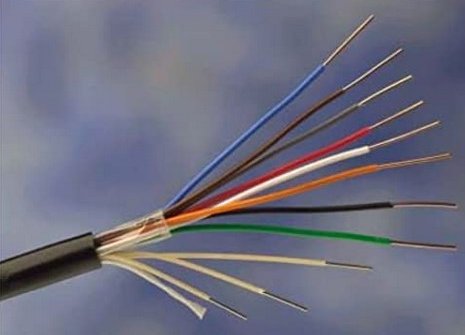
with 4 conductors (coloured, orange, white, green and black). External, overhead cable. This is a black, round cable
with 4 conductors (coloured, orange, white, green and black).
It is self supporting for up to 68metres and had around 3 steel
0.25mm suspension wires (yellow covered) which were not to used electrically.
Specification
CW1378 (10)
CW1411 (10B)
Conductor
0.5mm
Plain Annealed Copper Wire (PACW)
Insulation
Solid
High Density Polyethylene
Diameter
over Insulation
1.02mm
Core
wrap
Polyester Tape
Support
strands
Brass
Plated Steel, 3 elements of 3 x 0.25mm strands,
each
element PVC
Ripcord
Nylon
Colour code
Pair
1: Orange/White
Pair
2: Green/Black
Dropwire No. 11
 The
cable contains one 0.5mm plain solid copper pairs insulated with
solid
polyethylene and wrapped with a polyester tape, three
elements of
3 x 0.25mm brass coated steel support strands insulated
with PVC,
and is sheathed overall with a medium density black
polyethylene sheath. The
cable contains one 0.5mm plain solid copper pairs insulated with
solid
polyethylene and wrapped with a polyester tape, three
elements of
3 x 0.25mm brass coated steel support strands insulated
with PVC,
and is sheathed overall with a medium density black
polyethylene sheath.
Specification
CW1415
Conductor
0.5mm Plain Annealed Copper Wire (PACW)
Insulation
Solid High Density Polyethylene
Diameter
over insulation
0.93mm
Core
wrap
Polyester
Tape
Support
strands
Brass Plated Steel, 3 elements of 3 x 0.25mm strands,
each
element PVC Insulated
Colour
code
Pair 1: Orange/White
Dropwire No. 12
This
cable is designed for overhead distribution lines, typically from a
telegraph pole to the customer’s premises.
The
cable contains one 0.9mm plain solid copper pair insulated with
solid
polyethylene and wrapped with a polyester tape, one element
of 3 x
0.41mm brass coated steel support strands insulated
with
PVC and is
sheathed overall with a medium density black
polyethylene sheath.

Specification
CW1406
Conductor
0.9mm
Plain Annealed Copper Wire (PACW)
Dielectric
Solid
High Density Polyethylene
Diameter
over dielectric
1.50mm
Core
wrap
Polyester Tape
Support
strands
Brass
Plated Steel, 1 element of 3 x 0.41mm strands,
PVC
Insulated
Ripcord
Nylon
Colour code
Orange/White
Dropwire No. 14
 Dropwire
No. 14 is a 4 pair black external cable, incorporating
brass coated steel stranded strain wires with yellow PVC insulation. Dropwire
No. 14 is a 4 pair black external cable, incorporating
brass coated steel stranded strain wires with yellow PVC insulation.
Conductor size
0.5mm.
Specification
CW1378.
Colour code
Pair 1: Orange/White
Pair 2: Green/Black
Pair 3: Red/Grey
Pair 4: Blue/Brown
 This
cable is designed for overhead distribution lines,
typically from a telegraph pole to the customer’s
premises. This
cable is designed for overhead distribution lines,
typically from a telegraph pole to the customer’s
premises.
The cable
contains four 0.5mm plain solid copper pairs insulated
with solid polyethylene and wrapped with a polyester
tape. It has three brass coated steel support
strands insulated with PVC,
Brass Plated Steel
and is
sheathed overall with a medium density black
polyethylene sheath.
Specification
CW1420
Conductors
0.5mm Plain Annealed Copper Wire (PACW)
Insulation
Solid High Density Polyethylene
Colour
code
Pair 1: Orange/White
Pair
2: Green/Black
Pair
3: Red/Grey
Pair
4: Blue/Brown
Clamps and Brackets
The following clamps and brackets are for use with some of the
Dropwire shown below.
Bracket No. 22A
Triangular shaped, Galvanised steel brackets used in the fixing of dropwire
cables to poles or walls.

Bracket No. 22A
Bracket No. 32
Galvanised steel bracket used in the fixing of dropwire cables to poles or
walls. These brackets have a loop on an extended arm to allow the attachment of
various drop cable clamps or helical cable clamps.

Bracket No. 22A
Clamps, Dropwire No. 6A
A coated metallic spiral clamp approximately 220 mm long. Used to
attach either a dropwire No. 10, 11 or 12 inside a Hollow Pole. Designed to be
wrapped around the dropwire, not the wire around the clamp.

Clamps, Dropwire No. 6A
Clamp, Dropwire No. 10A
Stainless steel dead end clamp for fixing drop wire at pole or premises'
termination points.
Length
430mm
A coated
metallic spiral clamp approximately 430 mm long. Used to attach either a
Dropwire No, 10B, 11 or 12 to a
Pole
ring or any dropwire fixing.
The
clamp is designed to be wrapped around the dropwire, not the wire around the
clamp.

Clamps, Dropwire No. 10A
|