OVERHEAD CONSTRUCTION
| ||||||||||||||||||||||||||||||||||||||||||||||||||||||||||||||||||||||||||||||||||||||||||||||||||||||||||||||||||||||||||||
|
Click here for Overhead Construction Menu Click here for a Pole Erection Party in action using Lifters and Ladders P.O. ENGINEERING DEPT POLING 1. General 2. No rigid rule can, however, be laid down as to the sizes which should be erected by one method or by another. The position in which the pole is to be erected should have consideration in determining the method to be used. For instance, on replacement work where the existing pole is suitable for use as a derrick, a saving in labour can sometimes be made by using the derrick method for a pole which would otherwise be raised by means of ladders. 3. Equipment 4. Care should be taken to ensure that all equipment used in pole erection is in a sound condition, and of adequate strength for the work in hand. Particulars of safe working loads for various sizes of rope are given in TOOLS AND TRANSPORT, Mechanical Aids, B1002, and details of the mechanical advantage obtained by various arrangements of blocks and tackle and the stress on the different parts, in TOOLS AND TRANSPORT, Mechanical Aids, B1005. The weights of wood poles are given in C1101 and on Card TE706.
FIG. 1 - POLE CART 5. Pole Cart 6. Pole Sliding Boards facilitate the erection of poles in 'stepped' holes. They act as a guide and provide a smooth surface down which the butt of the pole slides without displacing soil, ,etc., into the bottom of the hole. 7. The boards, which should be obtained locally, should be made from best-quality pitch pine, free from shakes or other defects, and painted with one coat of wood priming and two coats of lead colour ; well-seasoned elm or ash may be used if pitch pine is not readily available. For poling generally, plain boards, 7 ft. x 10¾in. x 1½in., will suffice. For protection, the ends of these plain boards should be bound with hoop-iron. For the erection of long or heavy poles, the boards may be reinforced by strips of 1½in. dia., half-round wrought iron, placed lengthways on the front of the boards at 6½in. centres, and secured by 1½in. No. 14 countersunk screws at 8in. intervals. Four cross-pieces of wrought iron, 2in. x 3/8in. x 10¾in., should be secured by means of 1½in. No. 14 screws to the back of the board, two being placed at the extreme ends and two at 1 ft. from the ends. Hand-holes, 2in. x 5in., may be cut 3½in. from each end. 8. Pole Lifters (Fig. 2), for use in the erection of poles in cylindrical holes and in the earlier stages of the erection of heavier poles, are made in four lengths, viz :-10, 12, 14 and 16 ft. If preferred, stout ladders of suitable lengths may be used instead of the lifters, the latter being entirely dispensed with. When a heavy pole is being raised, pole lifters should be used only in conjunction with ladders; the lifters should not be relied upon to take the weight of the pole.
9. A "Handle, Lifter, Pole" 10. Ladders
FIG 3 - WIRE RUNG ON LADDER 11. Four 7ft. lengths of "Wire, Galvd., Line, 400lb." are passed through the holes so that equal lengths project from either side of the ladder. Between the stiles, the wires are bent so as to provide a dip of 2in. in the middle of the rung. The free ends at each side are then wrapped tightly, in pairs, round the stiles - one pair 11 turns in one direction, and the other pair 11 turns in the opposite direction. The two pairs at the inner side of one stile are brought together and wrapped closely and tightly, side by side, round the four centre wires to within 2in. of the other stile. The pair nearer this stile is then cut off and the ends pressed home, and the other pair unwrapped to within 2in. of the first stile and cut off. The two pairs at the opposite stile are then similarly wrapped in the remaining gaps, to meet the pairs first dealt with. Finally, the wires are cut and the ends pressed home so as to leave no gaps or sharp edges. 12. Pole Jacks
Pole Jack 13. "Line, Sash, No. 12" is normally used for guy lines. Sash line should not be relied upon, however, if failure of the guy line would involve risk of injury or damage; rope should always be used in such circumstances. 14. Rope 15. "Twisters, Pole" Issue 5 additional
FIG. 4 - POLE TWISTER (1937)
FIG. 4 - POLE TWISTER (1960) 16. "Crowbars, No. 1" are used during erection to guide the foot of the pole and, upon erection, when it is necessary to trim the hole or twist the pole to get it into the required position. 17. "Shovels, Gravel, No. 3" or "Spades, Trench", "Punners, Wood" (or "Punners, Iron" as preferred) and "Brooms, Bass" are the appropriate tools for filling-in. Digging bars - see para. 18 - are used instead of punners in cylindrical holes. 18. "Bars, Digging" 7ft. long, have one chisel end, and one punner end. They are used in cylindrical holes to act as a slide for the butt of the pole during erection and to consolidate the soil when filling-in, see paras. 23 and 50.
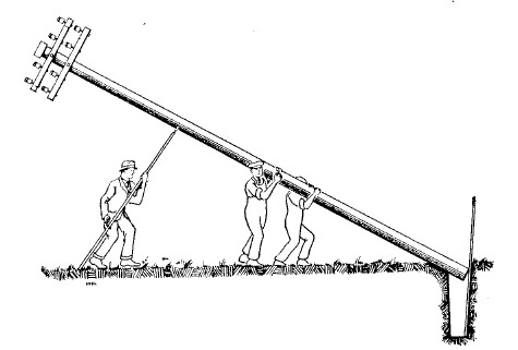
19. "Blocks, Double and Treble, 1in." and "Rope, Hemp, 3in." are required in derrick work for the main lifting tackle; "Chains, Sling, 4ft. or 6ft." and "Blocks, Snatch" are used in conjunction with this tackle. The sling chains are fitted with a small ring at one end and a larger ring at the other. The smaller ring passes through the larger ring ; no hook is required. 20. "Blocks, Single and Double", and "Rope, Hemp 2in." are generally used when luff tackle is required. "Winches, Crab" may be used in place of luff tackle, when convenient. 21. "Crowbars, No. 2" 22. Erection. Poles set in Cylindrical Holes 23. A digging bar should be placed against the side of the hole opposite to that from which a channel has been cut to receive the butt of the pole. To raise the pole to a vertical position, the butt should be placed in position in the channel and against the bar, and two men should place themselves one on each side of the pole in such a position that, when it is lifted, the pole is overbalanced towards the butt. Pole lifters or ladders should be used to assist in raising and to take the weight of the pole, as required. An illustration of this method of erection is shown in Fig. 5. 24. Erection. Poles set in stepped holes, using Lifters and
Ladders 25. To raise the pole, the men should arrange themselves behind one another, in the order of the height of their shoulders, near the tip of the pole, and lift. As the top of the pole is raised, the pole cart should be moved forward towards the pole hole, to support the pole while the men move forward to lift again. This operation should be repeated until the pole is raised sufficiently to allow the pole lifters and/or ladders to be brought into use. By gradually working these towards the foot of the pole which, at the same time, should be assisted by means of a crowbar or punner to slide into the hole, the pole is then raised to a vertical position. The pole cart should be used, if possible, until the pole is raised clear, when the weight should be taken by the ladders. 26. In raising A-poles, assistance may be obtained by the use of a pole jack. The jack should be placed firmly on a stayblock (or on the "base-joist") so as to be inclined slightly towards the pole hole. It should be as far from the butt end of the pole as is practicable, additional stayblocks being used as required to adjust the height or provide a firm base. A heavy stayblock should be placed transversely between the jack and the pole, and the jack should be central with both pole and stayblock. The jack should be operated to lift simultaneously with the men using the ladders. 27. On replacement work where the new pole is to be set near the existing pole, erection may be facilitated if a rope, secured to the head of the pole for use as a guy line, is passed over an arm on the existing pole and used in conjunction with the ladders during the later stages of erection. 28. The use of a Derrick is normally required for long and/or heavy poles, i.e., generally, single poles over 45ft. and A-poles over 40ft. in length. 29. When such a pole is to be erected in a new situation, it is necessary to erect a temporary pole to serve as a derrick. A sound medium or stout pole, slightly longer than half the length of the pole to be erected, should be used ; e.g., a 30ft. derrick suffices for a 50ft. pole. The derrick pole should be set in the ground to a depth of at least 3ft. If the ground is at all soft, the derrick should rest on a block of timber at the bottom of the hole and the hole should be increased in depth so that the bottom of the derrick is at least 3ft. below the ground line. 30. On replacement work it is sometimes possible to use an existing pole as a derrick, but the pole should be examined to see that it is quite sound and capable of withstanding the stresses that may be put upon it. 31. Guy ropes or stays in three or four directions should be attached to the derrick pole. If more suitable facilities for attachment are not available, the guy ropes or stays should be secured to crowbars fixed in the ground, or to temporary stay-rods and blocks. 32. Two methods of erection by derrick are available, known as the "Middling" method and the "End-on" method. These are illustrated in Figs. 6 and 7. The method adopted should depend on the space available for the operation, but the "Middling" method is preferable and should be used where circumstances allow, as the stresses imposed upon the derrick pole are not so severe.
33. "Middling" method 34. The double block should be attached to the main pole by means of a sling chain, so fitted that when raised from the ground the pole will be slightly "butt heavy." Three or four guy lines should be attached to the main pole for the purpose of steadying it during the course of erection. A guy line, attached about 3ft. from the foot of the pole, will be found useful for controlling the butt while the pole is being raised. The pole should be raised gradually until the point of balance is sufficiently high to enable the pole to be swung into a vertical position, with the butt just clear of the ground. The pole sliding board should be placed vertically at the deep end of the hole, the butt guided into position over the hole, and the tackle run out to allow the pole to drop into place. 35. For specially-heavy poles, the running end from the main tackle should be brought down the derrick to a 1in. snatch block attached to the derrick near the ground line by means of a sling chain. The chain should be prevented from slipping upwards by a pole bracket ("Bracket, No. 7"), or a pole step inverted and secured to the pole by means of coach screws. After being passed through the snatch block, the main tackle rope should be attached by means of a "Single or Double Blackwall" hitch (see TOOLS AND TRANSPORT, Mechanical Aids, B1003, when available) to the double block of a set of ¾in. single and double blocks with 2in. rope, known as the "luff" tackle, the single block of which is held in position by one or more crowbars driven into the ground or by other means if facilities for obtaining a secure hold exist, see Fig. 6. 36. If desired, a crab winch (described in TOOLS AND TRANSPORT, Mechanical Aids, B1008) may be used in place of the lull tackle; when this is done, great care should be taken to anchor it securely to the ground. 37. "End-on" method
FIG. 7 - "END-ON" METHOD OF ERECTING HEAVY POLES 38. The following points should be borne in mind in connexion with the erection of heavy poles:-
39. Use of Crane-Lorry 40. Number of men required for erection. Pole erection should be undertaken only with an adequate number of men. In deciding upon the man-power required, the safety of the men and of the public should have first consideration. 41. Conditions for the erection of poles vary considerably, depending upon the position, accessibility and character of the site, proximity and class of highway, whether the poles have to be entirely manhandled, equipment available, weather conditions, and experience of the foremen and other men employed. It is therefore impracticable to lay down a hard and fast rule as to the number of men required for the erection of each size of pole under all conditions. Each job should be dealt with on its merits, and special consideration should be given to erection where conditions necessitate the provision of extra strength and/or precautionary measures for the prevention of accidents. 42. The minimum number of men, including the foreman but not including "watchers", to be employed for erecting poles under easy, straightforward conditions and with no mechanical aids, other than those described in this Instruction, is prescribed in Tables 1 and 2. TABLE 1
Note * - 7 men if conditions necessitate the use of a derrick.
43. Setting 44. Comparison with the profile of the wall of a building will assist in the determination of correct pole-setting, and advantage should be taken of this facility in built-up areas, where pole alignment is of particular importance. Care should be taken to ensure that poles set on gradients are not inclined downhill. 45. Stayed poles 46. Direction of arms 47. Fig. 8 illustrates a simple method of locating .a view point (about 7yds. from the pole is usually convenient) from which, by sighting along the arms, their correct alignment relative to the direction of the line can be determined. With a measuring tape or length of sash line, measure from the armed side of the pole equal distances A-B and A-C along the direction of the line. Then locate the point required - D - equi-distant from B and C. This can be indicated by the mid-point of a 20yd. length of sash line, the ends of which are held at B and C. The distances shown in Fig. 8 are generally suitable for pole positions in straight sections of line and at terminal points. Some increase or reduction in these distances is desirable at appreciable angles in the line, depending on the position of the view-point, outside or inside the angle. NOTE:- Since the direction of angle and transverse stays and struts will usually be determined by sighting along the arms, it is important that the direction of the arms should be determined with especial care.
FIG. 8 48. Twisting.
49. Filling in 50. Cylindrical holes 51. Reinstatement. 52. Numbering 53. Blocking 54. To obtain full advantage from blocking, the stayblocks should be placed in such a direction as to counteract most effectively the stresses on the pole. Thus, at terminal points, the blocks should be fitted at right-angles to the direction of the line, in accordance with C3301; at intermediate points, where blocks are required to counteract transverse stresses, they should be placed longitudinally, as shown in Fig. 9. Further, care should be taken to ensure correct shaping and adequate depth of the hole, and thorough consolidation of the soil. 55. Normally, two blocks should be fitted, one at about one-third of the depth of setting below the ground line and the other on the opposite side of the pole at the extreme butt. A medium or heavy stay-block, depending on the capacity of line and/or the character of the soil, should he used for the upper block. A light stayblock will generally suffice at the butt, owing to the greater earth resistance at the lower position. Where the stresses tending to deflect, the pole will be in one direction only, or are likely to predominate in one direction, the upper block should be fitted on the side to which such stresses will tend to pull the pole. 56. Except, in unsuitable soil, a single stayblock at about one-third of the depth of setting will generally provide all the additional support required for a light pole. 57. The pole should be cut at the butt to fit the lower block as shown in Fig. 9, but it should on no account be cut for the purpose of fitting the upper block. The cut surface should be liberally treated with " Creosote and Tar." The blocks should be secured to the pole by means of 5/8in. arm bolts, with "Washers, Galvanised, No. 8" in place of the ordinary arm-bolt washers ("Washers, Galvanised, No. 4").
FIG. 9. - METHOD OF BLOCKING POLES 58. In fitting the upper block, it is more convenient, to fit the bolt to the pole before the pole is erected, and leave the block to be fixed in position after the pole-hole has been filled-in to a point level with the underside of the block, i.e. 5in. below the bolt. When filling-in has been completed to this point, the bolt should be partly withdrawn and the pole-hole carefully trimmed, so that the block may be wedged tightly between the pole and solid, undisturbed earth, and, afterwards, bolted to the pole. If attached before the pole is erected, there is a distinct likelihood of the upper block obstructing setting and filling-in operations and, also, of the pole-hole being incorrectly trimmed to receive the block, thereby reducing the efficiency of the foundations. 59. Poles in unstable ground
FIG. 10. - BLOCKED POLE IN UNSTABLE GROUND 60. Unloading and handling poles 61. When skids are not used it is sometimes necessary, after lowering one end of a pole from the side or back of a vehicle, to let the other end fall to the ground. In such circumstances the pole should always be unloaded tip end first, and always where it will fall clear of obstructions such as railway metals or granite kerbs. If unloaded butt end first, the tip end vibrates on striking the ground and the pole is liable to be sprung or broken. 62. When carrying poles, the workmen should arrange themselves in the order of the height of their shoulders and each man should use the same shoulder When placing the pole on the ground, it should not be thrown off the shoulders, but should be lowered to arm level and then, tip first, to the ground. 63. Lifting heavy poles over buildings 64. Stacking 65. Prevention of Accidents
|
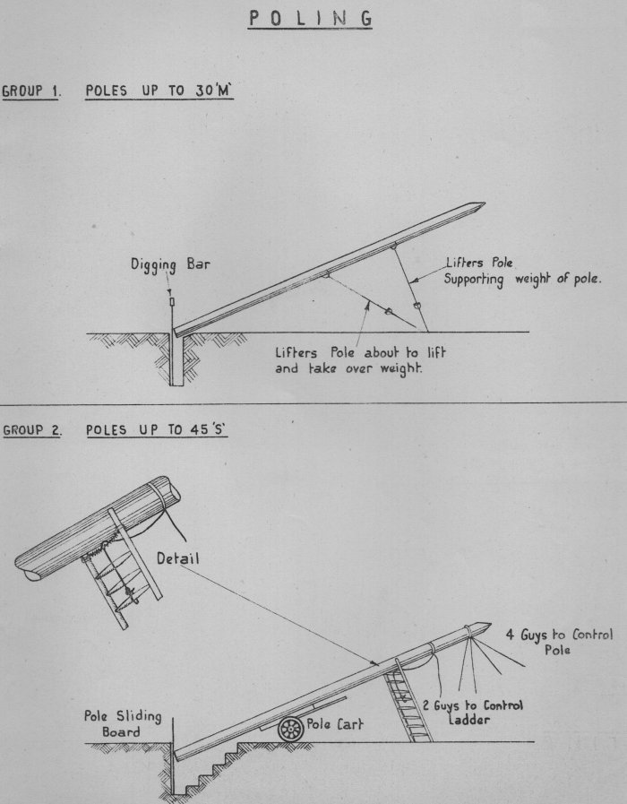
||||||||||||||||||||||||||||||||||||||||||||||||||||||||||||||||||||||||||||||||||||||||||||||||||||||||||||||||||||||||||||
Last revised: March 29, 2023FM2 | ||||||||||||||||||||||||||||||||||||||||||||||||||||||||||||||||||||||||||||||||||||||||||||||||||||||||||||||||||||||||||||