OVERHEAD CONSTRUCTION
| |||||||||||||||||||||||||||||||||||||||||||||||||||||||||||||||||||||||||||||||||||||||||||||
|
The History and Development of Insulators INDUSTRIAL archaeologists will be familiar with the sight of porcelain insulators used to support overhead telephone and telegraph wires; these are often to be found on old buildings and at sites of industrial archaeological interest. However, so far as the author is aware, no detailed account of the history and evolution of this type of insulator has ever been published. Such information that is available is widely scattered and not readily accessible. It will probably come as a surprise to many industrial archaeologists to discover that some of the insulators still in use are over a hundred years old. This applies not only to railway installations, but also to industrial buildings which, in themselves, may be worthy of attention. It is generally true that most items of railway operating equipment disappear from use long before they become of interest to the industrial archaeologist. For a long time, one notable exception to this state of affairs has been the continued use of insulators for supporting overhead transmission lines; however, rapid progress is now being made in replacing all overhead lines with surface and underground multi-channel cables. Only some twenty years ago, nearly every major road was accompanied by a line of telephone poles, sometimes carrying as many as a hundred individual wires; already these have almost entirely disappeared, generally being replaced by underground cables. Even where overhead transmission lines survive, usually in rural areas, conventional insulators are now being dispensed with, through the use of plastic insulated transmission wires, attached to the arms of poles by plastic-coated support wires. However, despite the closure of so many branch railways, where much of the oldest telegraph equipment was to be found, considerable distances of overhead lines still survive throughout large areas of the country. These provide a rather neglected field of real interest, which deserves attention before the remaining evidence disappears. Overhead transmission lines have been used for a wide variety of communications purposes, apart from telephony and telegraphy. Railway operating applications include block circuit telegraphy, signal repeaters, track circuiting, signal light and point position indicators, as well as public address systems. Other civilian uses include telemetry, e.g. to provide remote indication of the depth of water in reservoirs, or in rivers liable to flooding. The first recorded use of insulators for a commercial overhead telegraph transmission line occurred when the original GWR circuit of 1838, from Paddington to West Drayton, was reconstructed. Work began in 1842, and the telegraph line was extended to Slough during 1843. By 1854 extensive route mileages were in general use, mainly by railway companies. Dr Dionysius Lardner lists forty railway companies in the UK using telegraphic communications; brief details of the installations of a few of the companies are given in Table 1. By the same date, most major towns and cities were linked by telegraph services available to the general public. As an example of the tariffs then being charged, a message of twenty words cost 1s 0d (5p) for 5o miles, 2s 6d (12½½p) for too miles, and 5s 0d (25p) for greater distances. TABLE 1
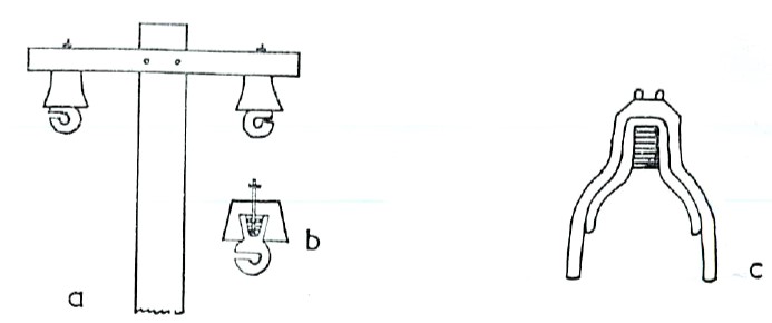
The very first types of insulator to be used consisted of polished wood blocks, examples of which can be seen at the Post Office Tele-communications Museum, London. However, these were found to be far from satisfactory for supporting bare wires and have long ago disappeared from use. They were superseded by the widespread introduction of tubular insulators' which in their turn were replaced by types of insulation essentially similar to those still in general use today. Tubular insulators consisted of tubes made of glass or ceramic which were attached directly to the supporting pole. Conducting wires, generally of iron coated with a protective layer of zinc and about ,in diameter, passed through the tube insulators. At intervals of approximately half a mile, the wires were tensioned at 'winding posts', illustrated in Fig 1B, in order to prevent undue sag. Before the use of winding posts, much inconvenience was caused by sagging wires coming into contact with each other during high winds, or through being earthed by touching neighbouring tree branches. Owing to their high rate of corrosion, particularly in industrial areas, iron wires were gradually superseded by steel and then by copper alloy. The latter have a much higher electrical conductivity and a greater resistance to corrosion, which more than justified the increased cost involved.
Fig 2 Tubular insulators proved unsatisfactory under conditions of high humidity, owing to water condensing on the surface and thereby allowing some of the electric current to leak to earth. This leakage was seriously enhanced in industrial regions through two factors. First, dust and smoke soon formed a carbonaceous layer over the surface of the insulating material, greatly reducing its electrical resistance and also encouraging the adsorption of water vapour. Secondly, the gases evolved in the combustion of coal contain substantial proportions of materials which, when dissolved in water, form highly conducting acidic solutions; the most important of these gaseous substances arc sulphur dioxide and carbon dioxide. In an attempt to minimise surface conduction due to moisture and smoke deposits, the 'water shed' type of insulator was introduced. This involves constructing the insulator in the form of an inverted cone, so that the lower surface is protected from dust and rain. In its earliest form (Fig 2A), the shed insulator consisted of a galvanised iron cone, the upper end of which was joined to a threaded rod which bolted on to the arm of a telegraph pole. A ceramic hook to support the telegraph wire was cemented into the base of the cone, as shown in Fig 2B. However, this design was soon rendered obsolete by insulators incorporating a hollow, ceramic cone; this offered greater protection both from dust deposits and from surface moisture.
Fig 3 An example of an early American (House's type) insulator constructed in this manner is shown in Fig 2C; the insulating material, glass or ceramic, forms the inner cone which screws on to a wooden support. The inner cone is cemented into a heavy galvanised iron outer cone, which serves both to protect the insulating material from damage and to keep it clean and dry. Insulators of similar design were used in the UK, hut have normally long ago been replaced, on account of their considerable weight (about 5lb). Nevertheless, a few have survived in railway tunnels and under bridges, where the iron cone protects the insulator from dripping water and smoke deposition. An example, once used by the L & SWR, is illustrated in Fig 3A. This particular insulator was manufactured by Fuller of Bow; the vents in the iron cone were designed to allow driving rain to clean the inner, porcelain cone, into which the support spindle was cemented. Use of this type of insulator placed serious limits on the number of telegraph lines which could be supported by a pole, because of the weight involved. The problem was eventually solved by abandoning the metal cone part of the design, thereby leading to the introduction of types of insulator basically similar to those seen today. A double shed construction is most commonly used, since this has the effect of increasing the insulating surface and hence the length of the path for current leakage. Any material which is to be used in the construction of overhead line insulators must satisfy two fundamental requirements. Firstly, the resistance to flow of both ac and dc electricity must remain extremely high, whatever the relative humidity. The test specified by the GPO requires that the insulators shall be inverted in a shallow trough, which is filled with water to such a depth as to leave the outer shed of the insulator protruding half an inch above the surface. Water is also placed in the spindle hole and in the cavity between the inner and outer sheds; the insulator is then allowed to soak for twelve hours. To pass specification, the resistance between the spindle hole and the water in the trough must exceed 10,000 megohms at an applied potential of 500v dc. The second essential condition to be satisfied is that the insulator must be able to withstand atmospheric weathering, even in industrial atmospheres, for at least five years; the life of a glazed porcelain insulator may well exceed ten times this figure. Other highly desirable features of insulating materials are mechanical strength and a shiny surface which discourages the formation of a continuous film of condensed water and the adhesion of dust or smoke deposits. Brown or white leadless glazed porcelain was by far the best and most widely used constructional material: brown salt-glazed earthenware was also found, while a black pitch/asbestos fibre composition has been widely used in recent times, on account of its robustness and lower cost. Porcelain insulators can be manufactured from a mixture of china clay, ball clay, silica and feldspar in carefully controlled proportions.' The powder is ball milled, then sieved to - 120 BS mesh, after which any iron particles are removed electromagnetically. This is followed by removal of surplus water, using a filter press, and extrusion of the resulting paste into moulds. The pre-formed insulator is then thoroughly dried, inspected and fired; during the latter process, substantial shrinkage occurs, amounting to about one-seventh in height and one-tenth in diameter. Finally, the insulators are glazed: the object of the glaze is not to render the insulator non-porous, for it is already, but to reduce the adherence of dirt and to make cleaning easier. It has been shown that unglazed insulators stand up equally well to atmospheric humidity in unpolluted conditions. In order to ensure a complete absence of porosity, randomly selected insulators are tested by immersion in a 5 per cent alcoholic solution of fuchsin dye and subjected to a hydrostatic pressure of 2,000lb in sq for 24 hours. After this treatment, no dye penetration should have occurred. In fact, the extent of porosity in porcelain insulators is normally so low that water adsorption under the most adverse conditions is less than 0.001wt per cent. Stoneware, or earthenware, insulators are manufactured in an essentially similar manner, but the clay used contains appreciable quantities of ferric oxide. Glazing used to be effected by merely throwing common salt into the kiln. Earthenware insulators tend to fail more readily than those made from porcelain, owing to the development of fine stress cracks on ageing. Also they have a lower inherent mechanical strength. In recent times, black composition insulators have been used to a progressively increasing extent: their prime advantage is the low cost have been manufactured in white porcelain, brown earthenware and black fibre composition, although not in every case for the GPO. In addition, red-glazed porcelain insulators, corresponding closely to Post Office No. 1, have been used by various railway companies: some examples still survive on Southern Region lines. Exactly when the Cordeaux type of insulator was first introduced is not clear, but the name is probably taken from a patent by J. H. Cordeaux, dated 1877. It is interesting to note that Cordeaux's patent is illustrated with insulators of a markedly different shape from those described above. This patent actually covers the use of supporting spindles which screw into the body of an insulator; a fibre washer was to be placed between a shoulder on the spindle and the insulator, so as to avoid damage when the insulator was screwed down, or through thermal expansion of the spindle. Before this date, the supporting spindles were fixed into the insulator permanently by use of a kind of cement, a practice which is still occasionally used. During the second half of the nineteenth century, several other insulator designs were developed, in attempts either to improve performance or reduce costs. One of the most successful was the Langdon insulator, which was widely used by the Great Eastern Railway, the Great Northern Railway and also the Great Northern Railway (Ireland). The Langdon insulator comes in essentially two sizes; the larger is of three shed construction, shown in Fig 3G, while the smaller is very similar, but has only two sheds. Dimensions of these insulators are, typically, height 5¼in x diameter 4½in, and height 4¼iin x diameter 3¼iin respectively. Langdon insulators were usually made to fit on a 5/8in diameter screwed spindle, but examples fitting on to ¾in diameter spindles have been manufactured by Bullers Ltd. In so far as the author is aware, Langdon insulators have only been made in white glazed porcelain: they can still be seen on some Eastern Region lines. Another successful, but relatively expensive type of insulator dates from 1882, and is known as the Langdon and Fuller Patent. This is illustrated in Fig 3H. Typical dimensions are height 4½in x diameter 3¼in; the supporting spindle was normally cemented into the insulator, but examples having an internal screw thread also exist. Insulators of this type, made of white glazed porcelain, are known to have been used by the London, Brighton and South Coast railway on the Pulborough - Midlturst line. The London & South Western Railway also used Langdon and Fuller insulators, but made of brown glazed earthenware; examples were to be found on the Bishop's Waltham branch and on the West Moors - Alderbury Junction line, immediately prior to closure. The object of the corrugations round the circumference of the insulator is both to increase the leakage path and also to cause condensed water to break away from the surface in droplets, as well as facilitating evaporation. A type of insulator which was once widely used both by the railway companies and by the GPO is made of brown glazed earthenware (Fig 3J) and has the words Warley's Patent' impressed on the dome. Construction is of maximum simplicity, the inner shed being manufactured separately and cemented into the outer shed; the supporting spindle was then cemented into the body of the insulator. It is unclear which patent the inscription refers to, since C. F. Varley lodged a number of patents between 1860 and 1865, while others were lodged by S. A. Varley. Typical dimensions of a Varley's Patent No. 8 insulator (for 8swg wire) are height 4¼iin x diameter 3¼in; they were always constructed of brown glazed earthenware. Both Cordeaux's and Varley's Patent were in general use by the GPO during the last two decades of the nineteenth century, but the latter type gradually fell from favour. A very similar design of insulator, but constructed of white glazed porcelain, was used by the Great Western Railway and on the associated Cambrian Railway lines. Another type of insulator, somewhat resembling Varley's Patent, but smaller and conical in shape, is shown in Fig 3K. Typical dimensions are height 3½in x maximum diameter 3in; in earlier examples the supporting spindle is cemented in, but versions having an internal screw thread were manufactured during the twentieth century. As with Varley's Patent brown glazed earthenware examples (classified as type Z) were widely used by the London & South Western Railway and by the Somerset & Dorset Joint Railway: the Great Western Railway used similar insulators made of white glazed porcelain. All the insulators discussed so far were normally used for continuing overhead lines. Where an overhead line terminates and has to be connected to an insulated lead-in wire, which is attached either to the side of a building or directly to a pole, one of two types of insulator can be used. An earlier type, which is no longer easy to find, was invented by Messrs Sinclair & Aitken and is illustrated in Fig 3L. This insulator is constructed in glazed porcelain and consists of two separate parts which screw together; the inner cup has a deep groove cut in it to accommodate the insulated wire: The outer cup is screwed down to retain the lead-in wire, the end of which can then be joined to the overhead line which terminates at the insulator. A much rarer form of the Sinclair-Aitken insulator is used to terminate overhead transmission lines which have been carried down the side of a building via a spur insulator. This insulator (Fig 3M) resembles Fig 3L, but both the grooves on the outer cup are missing and instead a grooved knob, or spur, is moulded on to the side of. the insulator. The height (4in) and diameter (3½in) are the same for both figures 3L and 3m; Sinclair-Aitken insulators were usually made from white glazed porcelain and were. at one time quite widely used by the GPO. A far more common type of terminal and lead-in insulator was invented by Colonel Sir T. F. Purves and Mr J. Sinnott, destined to become Engineer in Chief and Assistant Engineer in Chief to the GPO. In its original form (Fig 3N) this insulator had an inner shed to prevent the lead-in wire coming into contact with the metal support spindle. However, the introduction of rubber- and lead-covered .lead-in wires soon caused the inner shed to be discontinued in the GPO specification, although the London & North Eastern Railway were still using insulators of this type immediately prior to nationalisation. In its present form, this insulator has no inner shed; two vertical holes through the body of the insulator lead to a recess at the top, which is covered by a screw-on cap. An insulated overhead line, which terminates at the groove, is led in a loop through the base of the insulator into the upper recess. There it is joined to the insulated lead-in wire, which enters via the other vertical hole; finally, the joint is protected by filling the recess with a pitch composition, or some similar material. Alternatively, there is a small hole leading direct from the groove to the top recess, through which a thin, bare, overhead wire can be passed. Two sizes of insulator conforming to this pattern (Fig 3P) have been used by the Post Office; the larger type, PO No. 17, is sin high x Sin diameter and fits on a in diameter spindle. These were in use up until World War II. The smaller type, PO No. 16, is 4½in high x 2¾in diameter and fits on a 5/8in diameter spindle. Prior to World War II, no 16 insulators had only one groove (Fig 3P), but post-war versions were all made with two grooves (Fig 3Q). They are extensively used by both the GPO and British Railways and arc almost invariably constructed of white glazed porcelain or black fibre composition. Very occasionally, a brown glazed insulator of this type may be found, while a remarkably similar green glazed insulator can be seen on some domestic electricity supply overhead lines. A side-knob version of the Purves & Sinnott insulator, for terminating wires which have been led down the side of a building, has also been quite widely used by the GPO. This is known as type No. 21 and is illustrated in Fig 3R; the height is 4½in diameter, with the side knob projecting 13/16in. Examples manufactured in white glazed porcelain and in black fibre composition were being installed by the GPO until quite recently. An alternative type having two side knobs, for terminating bare overhead lines, can also be found (Fig 3S), although no record of it appears in the Post Office engineering instructions since 1925. However, mention of it is made in a paper of 1908, so it does not appear to have been used to any great extent. In order to facilitate testing of very long overhead lines, it used to be common practice to fit test insulators at regular intervals, so that individual sections of the line could be isolated and checked separately. Test insulators arc similar in construction to Purves Sr. Sinnott terminal and lead-in insulators, but are somewhat larger (see Fig 3T), having a height of 5¼in and a diameter of 3½in. They are classified as type No. 14 by the Post Office and may be constructed of white glazed porcelain or black fibre composition; in both cases, the characteristic domed top cap is normally moulded from black fibre composition. A recess in the top of the insulator contains a cartridge fuse link, so that removal of the fuse isolates that section of the overhead line. Because long stretches of overhead line are becoming increasingly rare, very few test insulators still remain in use. An alternative version of this insulator contains a lightning arrestor, instead of a fuse link, in the top recess. Lightning arrestors can also be fitted in modified No. 16 insulators. The foregoing discussion has been deliberately confined to overhead line insulators used for communications systems by civilian authorities in the UK. Many insulators designed primarily for electric power supply purposes have, on occasions, been used for telegraph lines, particularly by railways. Some insulators can still be seen that were originally installed by the National Telephone Co, which operated telephone services on behalf of the corporations of Glasgow, Tunbridge Wells, Brighton, Portsmouth, I-lull and Swansea, at various periods between 1881 and 1914. Other types of insulator which can occasionally be found may sometimes have been imported (e.g. by the US armed forces during World War II) or else designed specifically for military requirements. A search of the patent literature will reveal numerous further designs for insulators, but generally speaking these have been manufactured only in small numbers, if indeed at all.
|
|||||||||||||||||||||||||||||||||||||||||||||||||||||||||||||||||||||||||||||||||||||||||||||
Last revised: December 11, 2025FM2 | |||||||||||||||||||||||||||||||||||||||||||||||||||||||||||||||||||||||||||||||||||||||||||||