| Extension users guide
Descriptive Leaflet - 1972
Descriptive Leaflet -
1978
POEEJ article on the P.A.B.X. No. 1 - 1954
Dictation control
Introduced in 1950
Private Automatic Branch Exchange No. 1
(P.A.B.X. No. 1)
Description
 The PABX No. 1 is a modern, automatic telephone system which effectively meets
the communication needs of small or medium sized businesses and commercial organisations. The system accommodates up to 10 exchange lines and 49 automatic extensions and provides
for automatic connection to the public telephone network and full internal dialling
between extensions. Incoming exchange calls are received on a small, compact, key-operated
switchboard on a table or desk, and are dealt with by the PABX operator. A small number of
manual extensions and lines to other PBXs can be connected to the system. Note: PBX means
either a Private Automatic Branch Exchange (PABX) or a Private Manual Branch Exchange
(PMBX). The PABX No. 1 is a modern, automatic telephone system which effectively meets
the communication needs of small or medium sized businesses and commercial organisations. The system accommodates up to 10 exchange lines and 49 automatic extensions and provides
for automatic connection to the public telephone network and full internal dialling
between extensions. Incoming exchange calls are received on a small, compact, key-operated
switchboard on a table or desk, and are dealt with by the PABX operator. A small number of
manual extensions and lines to other PBXs can be connected to the system. Note: PBX means
either a Private Automatic Branch Exchange (PABX) or a Private Manual Branch Exchange
(PMBX).
The automatic equipment is contained in a steel cabinet which has front and rear doors to
let the maintenance engineer get at both sides of the racks. Power to operate the
equipment is supplied from a secondary-cell battery linked with an automatically
controlled charging unit connected to the mains. The PABX 1 is available in four sizes.
Details are shown with the general information.
GENERAL FACILITIES
Extensions call each other simply by dialling the number.
Extensions make outgoing exchange calls by first dialling 9 for connection to an exchange
line. Any extension can be connected in such a way that it cannot dial 9 for an exchange
line but can get through to the public system only by way of the operator's switchboard.
Incoming exchange calls are first received at the switchboard and then extended to the
required extension by the operation of press-buttons.
A few manual extensions can be provided. Automatic extensions can call them direct but
they receive incoming exchange calls and make all outgoing calls through the switchboard. Lines to other PBXs can be provided. Extensions dial 7 for connection to an inter-PBX line
and in some instances it is possible over these lines to dial direct to extensions on a
distant PABX. On an outgoing exchange call, timing of the call stops and the exchange line
is released immediately the extension handset is put back. Extensions dial 0 to call the
switchboard operator.
SWITCHBOARD FACILITIES
The PABX 1 could be fitted with one of two types of switchboard. The early SA8120 version was made of wood, whilst the latter, SA 8133 type was of a modern design with the usual grey plastic
cover.
-
Extensions are called from the switchboard by press-button.
-
Ringing is automatically applied to extensions on calls from the switchboard.
-
Calls to or
from extensions are automatically released when the extension handset is put back.
-
If on
an incoming call the called extension is engaged the caller can wait and be automatically
connected immediately the extension is free.
-
The PABX operator can interrupt an engaged
extension to ask if another call can be accepted.
-
A ticking sound indicates that the
operator is on the line.
-
An incoming or outgoing exchange call can be held on the
switchboard by connecting it to a special holding number.
-
After holding, the call can be
connected to an extension by press-button.
EXTENSION FACILITIES
Calls between extensions are released when either extension handset is put back. On calls
to or from the exchange or another PBX, pressing the button on the telephone twice, calls
in the PABX operator, who can then hold the call or transfer it as required. An automatic
extension can, by pressing the button on the telephone once, hold an exchange call and
make an enquiry of another extension. The original call can be returned to by pressing the
button again; or if the handset is simply replaced the calls transferred to the other
extension. This operation can be repeated as often as required on the call. Manual
extensions do not have this arrangement. For night service there is a special key on the
switchboard. When this is in the `night service' position incoming exchange calls cause
suitably sited bells to ring continuously. Any automatic extension can then answer the
call by dialling 8, and can, if necessary, transfer it to any other extension. A different
kind of night service can be given by putting individual exchange lines through to
selected extensions.
 |
 |
| 5 + 24 |
10 + 49 |
TELECOMMUNICATIONS INSTRUCTION
C MARKETING INSTALLATION
3 Internal
F1016
Issue 1, April 1973
PABX's No. 1 AND 2
Installation of Equipment
SCOPE OF INSTRUCTION
This Instruction deals with the installation of PABXs1 and 2 in subscribers' premises.
RELEVANT TELECOM INSTRUCTIONS
F0301 gives a short general description of the PABXS; F1010 gives a detailed description
of the PABX 1 and F1014 of the PABX 2. F1011 and F1012 describe the cordless manual
switchboards for the PABX 1 and F1013 describes the automatic equipment which is used for
PABX's No. 1 and 2. Q0010 deals with the power plant required.
 |
 |
| Equipment Cabinet |
Battery Cabinet |
AUTOMATIC EQUIPMENT
(a) Equipment's, PABX, SA 8100 and Equipment PABX 1B ... /SA 8100
The equipment's should be stood directly on a level floor. It does not require special
fixing. If desired, the equipment may be made more manoeuvrable by lifting off the doors. For the equipment SA 8100.. a further reduction in weight and height may be obtained by
temporarily removing the plinth. This may be done by removing the appropriate screws as
shown on Drawing 90000, Sheet 3 for the 4 + 15 and 5 + 24 sizes (10 screws), and on Drawing 63959,
Sheet 3 for the 7 + 35 and 10 + 49 sizes of equipment (12 screws). The plinth or doors
must not be permanently removed.
The equipment's are partially equipped with Uniselector mechanisms in accordance with
Table 1. Where the requirements of an installation exceed the quantities given in Table 1,
the additional Uniselector mechanisms should be requisitioned separately and fitted
locally.
TABLE 1
| |
Exchange Lines |
Conn Circuits |
Inter-PBX circuits |
0-level circuits |
Uniselector mechanism |
| 4+15 |
3 |
3 |
- |
2 |
2/55A-P |
| 5+24 |
3 |
3 |
- |
2 |
2/55A-P |
| (1 B3) |
4 |
4 |
- |
2 |
2/10/2A-P |
| (1 B4) |
5 |
5 |
- |
2 |
2/10/2A-P |
(b) Jack-in equipment
The shelf-jack positions appropriate to the various relay-sets and selectors are given in
F1013 and F1021. On each equipment, there are two spare jack positions which may be used
as desired for the auxiliary Relay-sets, SA 8104, SA 8109 and SA 8144. Two relay-sets of
any one of these types or one each of any two may be fitted in these jacks. The jacks are
wired only with the common services wiring and additional wiring is necessary appropriate
to the relay-set fitted.
(c) Modifications to the equipment on installation:-
(i) Certain modifications are required to be made on equipment's, relay-sets etc, on or
after installation to cover retrospective changes agreed since the items were purchased.
These modifications should be made in accordance with the current works specifications
listed in D0020.
(ii) Modifications to the equipment to provide non-standard facilities on the PABX must
not be made unless prior approval of THQ(TD2.5.2) is obtained.
(iii) When 1 VF signalling inter-PBX circuits are required the equipment must be
modified and an Equipment, Signalling, No. 24/ ... provided. Installation details are
given in F1020.
(d) Relay-set SA 8104 modified for up to six circuits
Normally, Relay-set, SA 8104 is equipped and wired for three long-extension circuits (600
to 1000 ohms line loop) but, if necessary, it may be equipped locally for up to six
circuits, e.g. if there are, say, four long extensions and the second spare jack position
is in use for another type of relay-set.
The items required per circuit to extend the relayset are:-
1 x Relay No. 9763 (Relay LS) and
1 x Relay No. 9764 (Relay CO).
MANUAL SWITCHBOARD
(a) PABX 1
Switchboards PABX SA 8120 or SA 8133 are used. Switchboard SA 8133,which is of a more
modern design, supersedes SA 8120 for new work.
(i) The Switchboard, PABX, SA 8120 may stand on a desk or table. The base of the
switchboard can be secured to the table if the subscriber permits or desires this but it
should not usually be necessary. If the base is secured, access to the jack points for
wiring may be obtained by loosening two round-head screws, one at each side of the base.
Access to these screws is obtained by opening the sloping front panel of the switchboard. A dial or dummy dial, a telephone handset and lamps for the working circuits Should be
fitted to the switchboard, as appropriate. A cleat for securing the end of the cable from
the automatic equipment inside the switchboard should be made or provided locally. For
convenience in packing, the switchboard will be received with the receiver hook and handle
detached. The hook should be re-fixed on the end panel and the handle on the top of the
sloping front panel of the switchboard (see Drawing 63790/1).
(ii) The Switchboard, PABX, SA 8133 Mk 1 and Mk 2. Two
switchboards are currently available Mk 1 (Diagram SA 8133/0) and Mk 2 (Diagram SA 8133/1),
although the former will gradually be phased out. The Mk 2 can be distinguished from the
Mk 1 by the flexible cord (cord connecting No. 75/-1A) and lamps in the dial key speak
extension and speak exchange key. The switchboard may stand on a desk or table. A dial, a
telephone handset and lamps for the working circuits and alarms should be fitted to the
switchboard. For convenience of packing the switchboard will be received with the handset
cradle detached. This should be re-fixed on the left-hand side of the cover see Drawing
92612). An additional, Jack No. 84C may be fitted if required. The wiring for this is tied
back in the cable form. The jack is wired in parallel with the existing one. A connector
101/1A is required to terminate the cord connecting 75/1A to the 75 way cable.
(b) PABX 2
The Section, Switch, PBX, SA 7560 should be fitted, as required, with the miscellaneous
items listed on Drawing 90053. This drawing shows the positions of items which are special to
the use of the section with PABX 2, such as the dial cords for use with Relay-set SA 8141,
SA 8147 or SA 8148. it also shows the positions of the relay and resistor required if a
Key-sender is used instead of a dial. Drawing 63791 shows the, method of fitting Brackets,
Mounting EM. A Fuse Mounting No. 131B and Fuse No. 44A/1.5 for the 6v supply should be
fitted as indicated on Diagram LD 143.
As no cable turning section will be fitted, the cables from the automatic equipment and
the main frame will usually be taken into the switchboard through one end-panel which
should be cut locally to admit them. The Lamp, Alarm-indicating No. 5 in Case No. 24
should be fitted near the top of one end-panel, preferably at the same side as the
incoming cables so that only one end-panel need be cut. A Buzzer No. 33A in a Clip No. 91B
for audible alarms should be fixed inside the switch section.
Label Diagrams LD 141 and LD 143 should be obtained and pasted over the existing Diagrams LD
131 and LD 71 which are supplied with the section and pasted on the inside of the rear
panel.
Diagram LD 141 shows the cord circuit and associated wiring of the switch section when
used for a PABX 2. If the maximum number of 15 cord circuits are authorised the necessary
additional cords and pulley weights should be obtained and fitted locally.
Diagram LD 143 shows the cabling to be provided to jacks, lamps, terminal strips and
busbars and to the alarm unit. The face equipment should generally be arranged in the
following order:-
Left-hand panel
bottom - exchange lines
centre - automatic extensions
top - night service jacks
Right-hand panel
bottom - inter-PBX circuits
centre - manual extensions
MDF TERMINATIONS
Frames, Distribution No. 4 external circuits should be fused as indicated in Cl D1003.
Internal circuits should be taken via connection strips.
(a) Circuits between the MDF and the automatic equipment.
The cable sizes and number of
cables recommended for each size of equipment are as follows:-
4 + 15 size - one 41-wire cable
5 + 24 - one 41-wire cable and one 20-wire cable
1 B3 - two 41-wire cables and one 12-wire cable
1 B4 - three 41-wire cables
For the 4 + 15, 5 + 24 and 1 B4 sizes of equipment, these provide for the full capacity
of the installation less one pair of wires. For an installation of one of these sizes
requiring the full possible number of exchange lines, extensions and inter-PBX circuits it
will be necessary to run an additional single-pair cable between the MDF and the automatic
equipment. Generally, it will not be necessary to provide this additional pair of wires at
the outset.
For the 1 B3 size of installation the number and sizes of cable shown above will be
adequate for the full capacity and will provide also one spare pair of wires.
In addition, at each installation, a single-pair cable should be provided between the
MDF and the automatic equipment for the battery and earth lead to the internal night
bells, [see also (d)]. The terminations of the circuits on the automatic equipment for
PABX 1 are shown on Diagram SA 8119, Sheet 2 and, for PABX 2, on Diagram SA 8119, Sheet 4.
(b) Circuits between the automatic equipment and the manual switchboard.
(i) PABX 1 -
A 75-wire cable is recommended for all sizes of equipment. This will provide for the full
capacity of a 1 B4 size installation plus some spare wires. The cable should be completely
terminated irrespective of size of equipment. The terminations are shown on Diagram SA 8119,
Sheet 2. These terminations provide connections in the cable for all circuits, thus
allowing for growth of the installation up to its maximum capacity.
On the 1 B3 and 1 B4 sizes of equipment a third inter-PBX circuit may be connected. The
wires for this ate included in the 75-wire cable in the terminations as shown on Diagram SA
8119, Sheet 2. On the 1 B4 size of equipment, the 2nd inter-PBX circuit is only
provided as an alternative to a 10th exchange line as its connections to the manual
switchboard are over the same wires.
The colour scheme for terminating the 75-wire cable is shown in Table 2 for
switchboards PABX SA 8120 and SA 8133 Mk 1 and in Table 3 for switchboards PABX SA 8133 Mk
2.
The battery and earth leads from the automatic equipment to the manual switchboard are
included in the 75-wire cable, two wires being used for battery and a further two for
earth. With this arrangement the switchboard may be up to 25 yards from the automatic
equipment. Greater distances may be covered by making use of pairs from spare triples and
wiring these in parallel with the existing wires.
(ii) PABX 2 - The types and sizes of cables between the automatic equipment and the
manual switchboard and their terminations on the latter are given on Diagram LD 143 for all
standard circuits normally required. The terminations on the automatic equipment are given
on Diagram SA 8119, Sheet 4.
(c) Circuits between the MDF and the manual switchboard (PABX 2 only) Types, sizes and
terminations on the manual switchboard of cables for these circuits, e.g. manual
extensions and night-service circuits, are given on Diagram LD 143.
(d) Circuits from MDF to extension telephones and night bells These should follow
normal internal wiring practice. Cl D1100 deals with the distribution of earth to the
extension telephones for the enquiry facility. Diagram N 806 deals with the connection of
the earth at the telephone.
(e) Circuits from the power plant to the equipment busbars are dealt with in Q0071.
(f) Cable supports Elaborate cable racking is not necessary.
(g) Wire wrapping In accordance with Specification D2155.
Cross-connections etc on the automatic equipment must be made between tags of the
connection strips (SCA - SCE) at the top of the automatic equipment as indicated on Diagram SA
8119, Sheet 2, for PABX 1, and Sheet 4 for PABX 2, and according to the facilities being
provided at the PABX.
Marking wire cross-connections on PABX 1 only, must be made on early equipment's
between the extension M-tags and the tags on strip connection SCA indicated on Diagram SA 8119
Sheet 2. These wires are already provided on later equipment's and must be removed when
used for a PABX 2.
Other cross-connections, such as the provision or removal of straps on or from shelf
jack points, must be made as appropriate to the facilities to be given and the type of
public exchange to which the PABX works. Details of the connections, etc are given on the
SAW diagram of the circuit concerned.
ADDITIONAL WIRING FOR AUXILIARY RELAY-SETS
When using Relay-sets SA 8104, SA 8109 or SA 8144, all wiring to the shelf jacks, except
the common services wiring, must be provided locally. Wire, Wire Equipment 1500 series
should be used for connections within the equipment and should be tied in to the main
cable forms.
(a) Relay-set SA 8104
Three wires per circuit are required from the shelf jack points indicated on the relay-set
wiring diagram to tags A, B and H (on the equipment connection strips) of the auto
extension line circuits for which the long line circuits are required.
(b) Relay-set SA 8109
On PABX 1, four wires per relay-set are required from the shelf jack points indicated on
the relay-set wiring diagram to tags A, B, H and HL of the associated auto extension line
circuit and one pair of wires from shelf jack points 21 and 22 to the MDF via tags on the
equipment connection strip SCA. See Diagram SA 8119, Sheet 2.
On PABX 2 the connections required vary with the purpose of the relay-set and are
indicated on the relay-set wiring diagram. The connections to the manual switchboard are
given on Diagram LD 143.
(c) Relay-set SA 8144
Connections to the manual switchboard are given on Diagram LD 143. In addition, a pair of
wires per circuit is required from jack points indicated on the relay-set wiring diagram
to the MDF. These may be taken via spare tags on connection strip SCA in the equipment, if
desired.
LABELS
(a) Labels for the PABX 1 manual switchboard
(i) Switchboard, PABX, SA 8120
The switchboard is fitted with engraved Labels No. 88H, White for regular services. For
exchange lines, inter-PBX circuits and manual extensions, blank Labels No. 88H, White are
fitted. These labels should be sign written temporarily, with the appropriate designation
of the circuit concerned and arrangements should then be made for them to be replaced by
engraved labels.
(ii) Switchboard PABX, SA 8133
The switchboard is fitted with printed Labels No. 438 for all common services and for the
two 0-level circuits. Exchange lines inter-PBX circuits and manual extensions require
Labels No. 438, Clear, Hot Stamped in Black with the required designation. These should be
ordered as required from Factories Dept under the normal procedure. Up to three lines of
seven characters per line may be accommodated on each label.
The clear Labels No. 438 supplied with the switchboard should be temporarily sign
written and changed when the permanent labels are received.
Where an exchange name is longer than seven characters and cannot be abbreviated to
seven or less characters, the local engineering code (or traffic code if preferred) should
be used.
(b) Labels for the PABX 2 manual switchboard
For the stile casings, Labels No. 277 ... should be reversed and sign written locally with
a general circuit description, e.g. exchange lines, against the appropriate groups of
jacks. Engraved Labels No. 86A are included in the appropriate Labels, PABX, Set No. ...
[see (c)] for the automatic and manual extensions. For exchange and inter-PBX lines,
individual circuit numbers should be engraved on Labels No. 86A, White against each
circuit appearance. (Temporary sign written labels should be provided until engraved
labels can be fitted).
(c) Labels for relay-sets and selector
These labels are supplied in sets as follows:-
Labels PABX Set No. 1A for PABX 1, 4 + 15 (Drawing 91053)
Labels PABX Set No. 1B for PABX 1, 1, 5 + 24 (Drawing 91055)
Labels PABX Set No. 1C for PABX 1, 1, 1 B3 (Drawing 91057)
Labels PABX Set No. 1D for PABX 1, 1, 1 B4 (Drawing 91059)
Labels PABX Set No. 2A for PABX 2, 2, 4 + 15 (Drawing 91054)
Labels PABX Set No. 2B for PABX 2, 2, 5 + 24 (Drawing 91056)
Labels PABX Set No. 2C for PABX 2, 2, 1 B3 (Drawing 91058)
Labels PABX Set No. 2D for PABX 2, 2, 1 B4 (Drawing 91060)
The appropriate Labels PABX Set No. ... should be requisitioned and fitted in
accordance with Table 4. Blank labels are included in each set for those relay-sets which
have local circuit numbers, e.g. exchange lines. These labels should be temporarily sign
written whilst arrangements are made for them to be replaced by engraved labels.
The location of the labels on the relay-set or selector is as follows:-
1 x Label No. 379, White or Label No. 236, White on the test jack.
2 x Labels No. 237, White on the cover
1 x Label No.. 238, White on the cover
FUSES
The fuses required on the automatic equipment for all the standard circuits are listed in
Table 5. The position for these fuses may be seen from the sign writing provided on the
equipment fuse-mountings. In addition, there are two spare fuse positions (see Drawing 90000,
Sheet 5 for the 4 + 15 and 5 + 24 sizes and Drawing 93132 Sheet 6 for 1 B3 and 1 B4 or Drawing
63959, Sheet 5 for the 7 + 35 and 10 + 49 sizes) which are not sign written but are wired
to the two spare relay-set shelf-jacks (see C1115) which may be used for auxiliary
circuits, i.e. Relay-sets, SA 8104, SA 8108 or SA 8144. When any of these are fitted the
spare fuse positions should be approximately sign written locally and one Fuse No. 44A/1.5
inserted for each relay-set fitted (maximum two relay-sets).
The fuses required on the manual switchboard of PABX 2 are indicated on Diagrams LD 141 and
LD 143. The positions of the fuses are shown on the latter diagram which also shows a
typical marking for the manual extension circuit fuse positions. These must be wired and
sign written locally.
HEAT COILS
The equipment's are supplied fitted with Coils, Heat, A, Green in the release circuits of
the connecting circuit selectors. If these coils are blown or removed during installation
or testing they must be replaced by similar green coils. Coils, Heat, A, Brown must not be
used because their higher current rating may involve a fire risk.
TESTING
Before the installation is handed over for maintenance it should be tested in accordance
with F1017 (PABX 1) or F1018 (PABX 2).
KEYS
Each Equipment, PABX, SA 8100... or Equipment, PABX, 1B... /SA 8l00 is supplied with two
keys for the locks of the cabinet doors and two keys for the locks of the plinth doors.
All keys should be handed over to the maintenance staff.
TI produced from EI Telephones, PBXS, C3110
TELECOMMUNICATIONS INSTRUCTION
C MARKETING INSTALLATION
3 Internal
F1013
Issue 1, March 1971
PABX's 1 AND 2
Description of Equipment - Equipment P.A.B.X. SA 8100
General
Equipment, P.A.B.X., SA 8100 comprises the automatic equipment for P.A.B.X.s
No. 1 (see F1010). With alternative relay-sets fitted it is also used
for P.A.B.X.s No. 2 (see F1014). The equipment
is made in four sizes known as Equipment, P.A.B.X., SA 8100 (4 + 15), (5 +
24), (7 + 35) and (10 + 49), the numbers in these descriptions denoting the
maximum number of exchange lines and automatic extensions, respectively. The
equipments are not extensible.
A front and rear view of an Equipment, P.A.B.X., SA 8100 (5 + 24) is
shown in Figs. 1 and 2; similar views of 10 + 49 equipment are given in
Figs. 3 and 4.
Rack and cabinet
The apparatus rack is 5 ft. 11 in. high and is enclosed in a grey-enamelled
sheet-steel cabinet fitted with double doors at its front and rear. It
stands on a plinth, 1 ft. high, which is also fitted with doors at its front
and rear, and may be used as a cupboard for miscellaneous maintenance Items.
Two sizes of cabinet are used: one, 2 ft. 10 in. wide, for the two
smaller sizes of equipment and the other 3 ft. 9 in. wide, for the two
larger sizes.
All doors are fitted with locks and separate keys are provided: one for
the doors of the automatic unit and one for the doors of the plinth.
The cabinet doors close against a rubber jacket at the front and rear, which
helps to exclude dust and to suppress noise.
To facilitate taking the unit into subscribers' premises, e.g. through
narrow corridors, the unit may, if necessary, be detached temporarily from
the plinth, thus reducing its height by one foot.
Apparatus
Details are as follows:-
(a) Uniselectors (linefinders) are standard PO Type No. 2.
(b) Two-motion selectors (connecting-circuit selectors) are 100-outlet
2000-type.
(c) Relays are 600-type relays which are used for the extension line
circuits, 3000-type relays used for other circuits and High-speed relays for
certain functions, where their special characteristics are essential.
Equipment of shelves
The shelves are lettered alphabetically from the lowest shelf to the highest
on each side of the rack. Shelves A to F are at the front and G to H at the
rear. The equipment of each shelf is as follows:-
(a) Shelf A. - Line and cut-off relays for the extensions and apparatus
for the start and alarm, enquiry, night-service and engaged-test circuits.
Various resistors for these circuits are also fitted on this shelf on
Equipments, P.A.B.X., SA 8100 (7 + 35) and (10 + 49) only.
(b) Shelf B. - Connecting-circuit linefinders and 0-level linefinders.
Various resistors for the circuits on shelf A are also fitted on this shelf
on Equipments, P.A.B.X., SA 8100 (4 + 15) and (5 + 24) only.
(c) Shelf C. - Exchange-line and inter-P.B.X. circuit linefinders.
Also for the release-alarm circuits of the connecting-circuit selectors,
Coils, Heat, A. Green are fitted (Any Coil, Heat, A, Brown, fitted in these
mountings, should be immediately replaced by a Coil, Heat, A, Green as
Coils, Heat A, Brown are not suitable for use in the release-alarm circuit).
(d) Shelf D. - Banks and jacks for connecting-circuit selectors. Two
battery jacks are fitted at the right-hand end of the shelf.
(e) Shelf F. - Connexion strips for cabling the automatic equipment to a
cordless or a cord-type switchboard (i.e. P.A.B.X. 1 or 2).
(f) Shelf F. - Jacks to accommodate exchange-line relay-sets for either
cordless or cord-type switchboard working.
(g) Shelf G. - Jacks for enquiry, marker, 0-level, ringing and tone and
ringing-pulse relay-sets [see also (j)].
(h) Shelf H. - Jacks to accommodate inter-P.B.X. circuit relay-sets for
either a cordless or a cord-type switchboard. Also a jack for a manual
extension-line relay-set for P.A.B.X. 1. On Equipments, P.A.B.X., SA 8100 (7
+ 35) and (10 + 49), this shelf also accommodates three exchange-line
relay-sets (exchange lines 8-10) which are fitted in the first three jacks
on the shelf [see also (j)].
(j) Spare jacks. - Two spare jacks are available for plug-in relay-sets
and can be used for auxiliary equipments - Relay-set SA 8104 and/or
Relay-set SA 8109 and/or Relay-set SA 8144. The spare jacks are on
shelf H on Equipments, P.A.B.X., SA 8100 (4 + 15) and (5 + 24) and on shelf
13 on Equipments, P.A.B.X., SA 8100 (7 + 35) and (10 4 49). The jacks
are on the extreme right-hand side of the shelf on each equipment.
Strip-mounted equipment
The strip-mounted equipment in Equipments, P.A.B.X., SA 8100 consists of the
following:-
Extension-line circuits - SA 8101
Ringing start and alarm circuits - SA 8105
External-extension night-service circuit - SA 8112 (or SA 8108 on early
equipments.)
Strip-mounted circuits are not obtainable separately.
|
 |
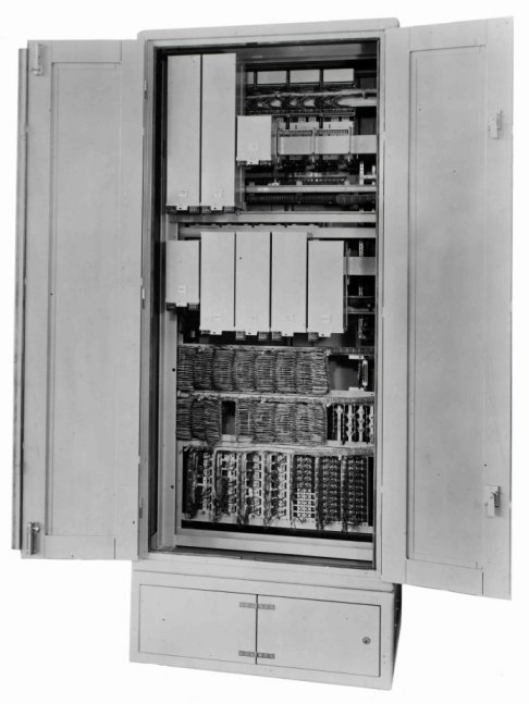 |
FIG. 1 - EQUIPMENT, P.A.B.X., SA 8100 (5 +
24)
FRONT VIEW |
FIG. 2 - EQUIPMENT, P.A.B.X.,
SA 8100 (5 + 24)
REAR VIEW |

FIG. 3 - EQUIPMENT, P.A.B.X., SA 8100 (10 + 49) - FRONT
VIEW

FIG. 4 - EQUIPMENT, P.A.B.X., SA. 8100 (10 + 49) - REAR
VIEW
Selectors and relay-sets
Uniselector banks are included in the equipment, when issued.
Uniselector mechanisms are provided in accordance with Table 1.
Two-motion selectors and relay-sets, together with any additional
uniselector mechanisms, are requisitioned separately. These are listed
in Tables 2, 3 and 4. The quantities necessary for particular sizes of
P.A.B.X's 1 or 2 are detailed in F1015.
Table 1
Basic Provision of Uniselector Mechanisms
| Size |
Exchange lines |
Connect circuits |
Inter-P.B.X circuits |
0-level circuits |
| 4+15 |
3 |
3 |
- |
2 |
| 5+24 |
3 |
3 |
- |
2 |
| 7+35 |
4 |
4 |
- |
2 |
| 10+49 |
5 |
5 |
- |
2 |
Table 2
Selectors and Relay-sets used for P.A.B.X 1 and 2
| Selector or Relay-set |
Description |
| SA 8102 |
Connecting-circuit selector |
| SA 8103 |
Enquiry circuit |
| SA 8104 |
Auxiliary circuits for long extensions |
| SA 8106 |
Ringing vi6rator and tone circuit |
| SA 8107 |
Ringing pulse circuit |
| SA 8109 |
Auxiliary circuit on automatic extension for long
private-circuit or inter-P.B.X. circuit to a P.M.B.X. |
Table 3
Relay-sets used for P.A.B.X. No. 1 only
| Relay-set |
Description |
| SA 8121 |
Exchange-line circuit |
| SA 8122 |
Marker and operator's circuit (superseded, for
new work, by Relay-set SA 8134) |
| SA 8123 |
Exchange-line circuit (superseded for new work,
by Relay-set SA 8121) |
| SA 8124 |
Manual extension auxiliary circuits (2 circuits
per relay-set) |
| SA 8125 |
Manual extension auxiliary circuits (4 circuits
per relay-set) |
| SA 8126 |
0-level circuits (2 circuits per relay-set) |
| SA 8127 |
Inter-P.B.X. circuit (B/W dialling) |
| SA 8128 |
Inter-P.B.X. circuit (d.c. signalling) |
| SA 8129 |
Inter-P.B.X. private circuit (generator and
balanced-battery signalling) |
| SA 8130 |
Inter-P.B.X. circuit (dialling-in from P.M.B.X.)
|
| SA 8131 |
Inter-P.B.X. circuit (B/W dialling between
P.A.B.X. or dialling-in from P.M.B.X., S.C.D.C. signalling) |
| SA 8132 |
Inter-P.B.X. circuit (B/W dialling between
P.A.B.X. or dialling-in from P.M.B.X., 1VF signalling, SSAC 13)
|
| SA 8134 |
Marker and operator's circuit |
Table 4
Relay-sets used for P.A.B.X. No. 2 only
| Relay-set |
Description |
| SA 8137 |
Exchange-line circuit |
| SA 8138 |
Exchange-line circuit [superseded, for new work,
by Relay-set 8137 |
| SA 8140 |
0-level lamp-lighting circuits |
| SA 8141 |
Inter-P.B.X. circuit (B/W dialling) |
| SA 8142 |
Inter-P.B.X. circuit (d.c. signalling) |
| SA 8143 |
Inter-P.B.X. private circuit (generator and
balanced battery signalling) |
| SA 8144 |
Manual private circuits (2 circuits per
relay-set) |
| SA 8146 |
Inter-P.B.X. circuit (dialling-in from a
P.M.B.X.) |
| SA 8147 |
Inter-P.B.X. circuit (B/W dialling between
P.A.B.X. or dialling-in from P.M.B.X., S.C.D.C. signalling) |
| SA 8148 |
Inter-P.B.X. circuit (B/W dialling between
P.A.B.X. or dialling-in from P.M.B.X., 1.V.F. signalling,
S.S.A.C. 13) |
Superseded relay-sets
Relay-sets SA 8122, SA 8123, SA 8138 have been superseded for new work.
So as not to complicate maintenance, the superseding and superseded
relay-sets must not be used together at the same P.A.B.X. Relay-set SA
8134 must be used when Switchboard P.A.B.X. SA 8133 is fitted.
TI produced from EI Telephones, PBXS, C3115
TELECOMMUNICATIONS INSTRUCTION
MARKETING INSTALLATION
3 Internal
F1021
Issue 3, May 1973
DESCRIPTION AND INSTALLATION OF EQUIPMENT PABX 1B ...
/SA8100 FOR
STANDARD PABX's 1 AND 2
SCOPE OF INSTRUCTION
Instruction describes a modified version of the Equipment PABX SA8100.
DESCRIPTION
The equipment's are available in two sizes, 1B3(7 + 35) and 1B4(l0 + 49). The title in
Equipment PABX 1B.../SA8l00.
Externally the Equipment PABX 1B... /SA8l00 can be distinguished from the earlier
equipment as no plinth is provided and grey hinges replace the earlier chromium plated
ones.
Internally, jack-in relay-sets replace the wired in relays on shelf 'A' for the
extension line, start and alarm, enquiry, night service extension and engaged test
circuits. A new heat-coil assembly is fitted, although the former arrangement may be
encountered.
To increase manoeuvrability four holes are provided in the base to facilitate the
fitting of castors, if required.
The facilities of the equipment remain unchanged (F1010).
OTHER RELEVANT INSTRUCTIONS
This instruction should be read in conjunction with:-
F1010 - Description of the PABX 1
F1014 - Description of the PABX 2
F1013 - Description of the Equipment PABX SA8100
F1015 and F1016 - Planning and Installation of the equipment
LABELS FOR THE RELAY-SETS
See F1016 for details of the label sets. These should be requisitioned and fitted in
accordance with table 2.
WEIGHTS AND DIMENSIONS
| |
Dimensions |
| Equipment |
Unequipped weight |
Fully equipped weight |
H |
W |
D |
| 1B3 |
300kg (661 lb.) |
560 kg (1200 lb.) |
5' 11.5" |
3' 9" |
2' |
| 1B4 |
565kg (1239 lb.) |
565 kg (1239 lb.) |
5' 11.5" |
3' 9" |
2' |
Additional Pictures
 |
| Earlier Switchboard SA8120 with the P.A.B.X. equipment
cabinet in the background |
| |
 |
| Later Switchboard - Switchboard SA8133 |
|