PHILIPS
| ||||||||||||||||||||||||||||||||||||||||||||||||||||||||||||
iS3000 SeriesIntegrated Services Private Branch eXchange
The SOPHO iS3000 Series is designed to cover the communication needs of small to very large organisations. This series of ISPBX systems comprises five models which have been optimised to different business sizes with between 20 to 65,000 extensions.
Up to 14 iS3070 and/or iS3090 nodes can be linked together to form one large distributed ISPBX with up to 65,000 extensions. General Architecture
The uniform hardware architecture and common software platform provide a scaleable ISPBX system which can be tailored to meet the needs of practically any organisation, simply by adding applications. This uniform hardware platform is based on a distributed architecture which divides the platform into three functional modules:
This distributed architecture off-loads the central module of the critical and time consuming tasks of end-user equipment and improves the overall reliability of the system by separating it into modules. CENTRAL PROCESSOR MODULEThe Central processor Modules (CM) of the iS3000 Series are built around Motorola's MC68000 family of 32 bits microprocessors. The different requirements of the five models in terms of processing power, memory capacity, fault tolerance and the number of central access interfaces are accommodated by two implementation variants:
One common Operating System provides a uniform software platform for call processing, operational maintenance, system assurance and the various end-user applications of the iS3000 Series, all incorporated in System Software release 810. Freely configurable I/O ports enable the central connection of external applications such as a management system, a call logging device, a maintenance terminal, a toll-ticketing printer, ACD supervisor(s), or a remote service or management centre. Initial system configuration and subsequent software upgrades of all iS3000 models are performed by down-loading the system software and user-data from an Operational Maintenance PC. Single-card Central processor ModuleThe Central processor Modules of the iS3010, iS3030 and iS3050 share the same CPU card, the CPU 3000. This central card contains a 16 Mbytes Dynamic Random Access Memory (DRAM) module (which can be replaced by a 32 Mbytes DRAM module if required) for the storage of dynamic data and the execution of the software packages. Also 8 Mbytes (expandable up to 32 Mbytes) of non-volatile Flash EPROM memory (SIMMs) is present on the central card. This FEPROM memory is used to store the software packages and other data, which must be protected against a power failure. Optional, an Accelerator Module (AM) can be added on the CPU3000 card to increase the performance of the processor. Furthermore the CPU3000 card has one 10baseT Ethernet connector for CTI applications and for up- and downloading of system files via File Transfer Protocol (FTP). The CPU card also contains a daughter board with 6 V.24 interfaces (5 in case the Ethernet interface is used) for the connection of external equipment. For the Central processor Module of the single CPU iS3070 another CPU card is used, the Central Control Slice (CCS). It has a 16 Mbyte RAM for storage of dynamic data. The maximum number of ports for the single CPU iS3070 is 2,000. This single CPU card is used as basis in fault-tolerant systems. This makes future upgrading to a fault-tolerant system possible. For the CCS a distributed architecture is used for system back-up and I/O interfacing. These two functions are implemented in a Back-up and I/O Module (BIM) which connects to the central control slices via the Communication Interface External card (CIE). The BIM module contains a hard-disk for system software and user-data back-up and provides multiple I/O ports for central access of external applications. These ports can be configured separately to allow the connection of any mix of external applications. A typical configuration holds 6 V.24 ports (max. 24) and a modem for remote service access. Fault-tolerant Central processor ModuleThe iS3050, iS3070 and iS3090 can use a fault-tolerant Central Module to assure maximum system availability. Four identical Central Control Slices (CCS) operate in parallel, according to the Philips patented (4/2) concept. The 4 processors synchronously execute the same instructions that are continuously verified by an automatic error recovery algorithm.
This algorithm is implemented in hardware and ensures that a single or double bit fault and even a fault which has affected an entire instruction is detected and recovered without any system discontinuity. This continuous process of hardware verification ensures that a memory fault, a processor fault, or even the break-down of an entire CCS is ruled out instantaneously without the need for complex diagnostic software. The 4 Central Control Slices, from a software point of view, behave as one fault-tolerant Central Processing Unit with up to 16Mbytes (iS3050 and iS3070) or 32Mbytes (iS3090) of RAM memory for operating the system software and holding the user-data. On-board DC/AC power-supply circuits reduce the number of cards that can cause a failure to an absolute minimum. In the fault-tolerant Central processor Module also the BIM is used for system back-up and I/O interfacing. An overview of the available HW models with their possible Central processor Module configurations is given in the following table:
SWITCHING NETWORK MODULEA non-blocking Switching network Module (SM) is part of all iS3000 models. The SM consists of a single stage PCM/ TDM switching matrix and connects to the different Peripheral Modules (PM) by using multiple 2Mbits/s links. The physical implementation of the SM module is model dependent. Each PM contains a local switching network that can be connected in a non-blocking arrangement to one other PM. Models with multiple PMs are arranged in a non-blocking network by using additional Switching Network Slices (SNS), each with a capacity of 1024 x 1024 time-slots (1 for iS3050, 2 for iS3070 and up to 6 for iS3090). The Switching Network Slices of the fault-tolerant iS3050, iS3070 and iS3090 models can be arranged in pairs so that the back-up of one slice is provided by the second one without any system interruption. This fall-back principle ensures that an SNS failure only increases the blocking probability but does not affect the overall operation of the system. The iS3050 uses one Central Switching Network (CSN) slice when equipped with more than 2 PMs. PERIPHERAL MODULEThe Peripheral Module houses the plug-in boards that provide the interface to end-user equipment. The number of positions in a shelf depends on the iS3000 model. Each pair shares 32 time-slots of the switching network via a dedicated 2Mbits/s backplane bus. A few special positions have access to a full 2Mbits/s group. The different types of available plug-in boards can be freely mixed across the different positions. A plug-in board can be inserted in a free position without needing to disconnect the power or to restart the system. Each PM has its own AC/DC Power-Supply Unit (PSU) to keep the risk of common failure to an absolute minimum. A Peripheral Module Controller (PMC) takes care of the time-critical functions of the plug-in boards and provides traditional telephony resources, such as:
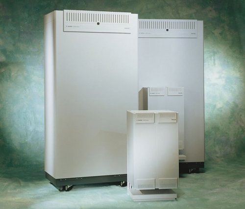
Additional tone sender/receiver cards can be added to the PM shelf in case of extreme traffic conditions. The software of the PMC is stored in flash-EPROM and is downloaded from the CM. This PMC software hides the central call processing software of the different signalling protocols and handles national variations in transmission plans. REMOTE PERIPHERAL MODULETo save in-premises wiring or to bridge longer distances, peripheral modules can be physically located more than 100 km from the central cabinet to act as remote concentrators. Connection is via 1 to 4 standard 2 Mbits/s links. This RPM option is supported on all models except for the iS3010. PLUG-IN BOARDSA wide variety of plug-in boards are available to interface an iS3000 system with all major types of analogue or digital extensions, business phones, public trunks, private tie-lines, cordless handsets, integrated announcers, paging equipment, operator consoles, voice processing systems, front-end office equipment, door openers and conference units. Each plug-in board has been carefully designed to support a maximum number of circuits (beween 4 and 32, depending on the interface type and the complexity of the wiring scheme). Multi-functional plug-in boards are provided to facilitate and optimise system configuration. This applies in particular to 2B+D ISDN and analogue cards which can be set in different modes: extension, trunk or tie-line. HousingThe light grey cabinets of the iS3000 Series have been designed to reduce installation time and to minimise the required foot-print. Different cabinet versions are available to house the different system types, optional Main Distribution Frames (MDF) and Remote Peripheral Modules (RPMs). All cabinets have a detachable front cover, which allows direct access to all printed circuit boards when it is removed. The room where the cabinets are to be installed should adhere to the ETS 300012 class 3.2 standard, which applies to partly temperature controlled locations. This means that heating, cooling, forced ventilation and humidification of the equipment room are not mandatory. SYSTEM CABINETA standard floor standing cabinet houses the largest models of the iS3000 Series. This cabinet is equipped with four swivel wheels for easy on-site transportation and has height-adjustable feet. Each cabinet can accommodate four PM shelves and can be coupled back-to-back or side-by-side by coupling strips to build larger configurations. The cabinets for the iS3010 and iS3030 may be wall-mounted or free standing on an optional floor stand. Both cabinets house one PM which has an optimised layout and size. MDF CAPACITY
MDF CABINETAn optional MDF cabinet can be delivered for all iS3000 models and RPM versions in case an external MDF is not available. All MDF cabinets have the same styling as the system cabinet. Cabinets can be placed side-by-side or back-to-back. The larger floor standing cabinet can be equipped with an internal MDF to save space. This MDF is located at the left hand side of the cabinet and is accessible through a separate door. This configuration is typically suited for small iS3050 or iS3070 configurations (up to 2 PMs) and is standard for the larger RPM version. The number of internal disconnecting blocks and external connection blocks for terminating the wires from the iS3000 line cards and the wires to the cabling system depends on the type of MDF cabinet. Protection against lightning and overvoltage is optional for all MDF versions. SYSTEM CAPACITY
1) the actual number of (usable) ports/subscriptions is
determined by the installed software license. RPM CABINETTwo cabinets are available for housing a Peripheral Module at a remote location. A compact wall mountable cabinet for one RPM (max. 288 ports) and a floor standing cabinet for two RPMs (max. 2 x 320 ports). These two cabinets have the same styling as the iS3000 system cabinets and only differ in the number of PMs. BIM HOUSINGFor the BIM module of the iS3070 and iS3090, an optional wall-mountable cabinet is provided. This small cabinet is in the standard iS3000 styling (height: 550 mm, width: 650 mm, depth: 450 mm) and can be mounted up to 15 m from the system cabinet. InterfacesThe list below gives an overview of the wide variety of interface types supported by the different plug-in boards of the iS3000 Series. analogue extensions:
digital extensions:
cordless extensions:
data communication:
analogue trunks:
digital trunks:
analogue tie-lines:
digital tie-lines:
auxiliary interfaces:Paging (ESPA), operator consoles, music on hold, voice mail, announcer, front office systems, conference units, door openers, etc. Technical DataCABINET SPECIFICATION
POWER SUPPLYAll iS3000 models and RPM versions, except for the larger iS3070 and iS3090, can be powered directly from the mains. An optional battery or Uninterrupted Power Supply (UPS) can be installed to provide continual operation in the event of a power failure. The iS3070 and iS3090 are powered from external DC source which can, if required, be mounted in a standard cabinet. Mains:
POWER CONSUMPTIONBy using 3 Volt CMOS technology, power consumption is extremely low. Typical power consumption figures are:
For digital extensions these figures depend on the connected terminals. Each digital port can supply power to one or more ISDN terminals in accordance to the ETS300012 standard (max. 4 W). PERFORMANCE
Performance figures depend on the system configuration and software release. TRAFFIC
TRANSMISSIONPulse Code Mode (PCM) coding in accordance with Alaw CCITT G711/712. SWITCHINGNon-blocking Time Division Multiplex (TDM) switching matrix of 64 kbits/s time-slots. SYSTEM AVAILABILITYState-of-the-art technology is used throughout all iS3000 models for reducing the number of system cards that can cause a failure to an absolute minimum. The larger models provide a fault-tolerant architecture capable of tolerating a card and/or link failure without any system discontinuity. System availability:
Mean Time Between (Fatal) Failure:
The above figures assume a mean time to repair of two days. EUROPEAN APPROVED INTERFACESConform to the European directive 91/263/EEC:
ELECTRO MAGNETIC COMPATIBILITYConform to the European directive 89/336/EEC:
SAFETYConform to the European directive 73/23/EEC:
ENVIRONMENTAL CONDITIONSConform ETS300019:
Temperature: -5'C to 45'C QUALITYIn accordance with ISO9001, including TickIT software certification. The information provided in this datasheet applies to all iS3000 models, unless stated otherwise. The products and services described herein are not necessarily available in all countries. As of 12/12/2001
|
||||||||||||||||||||||||||||||||||||||||||||||||||||||||||||
Last revised: June 02, 2026FM |