PNEUMATIC TUBE SYSTEMS
| |||||||||||||||||||||||||||||||||||||||||||||||||||||||||||||||||||||
|
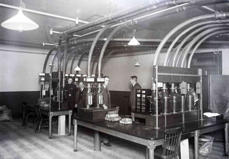
Pneumatic tubes became a good and secure method of sending information between buildings and the UK Government realised that Whitehall buildings could be connected via tubes. A self-contained government-only pneumatic tube network connecting offices all along Whitehall was started in 1918, with its hub in the basement of the War Office. It ran between the House of Commons and the Press Bureau in Whitehall with the Press Bureau terminal, and also connected to the Central Telegraph Office. By World War II the government tubes system had been expanded to connect 10 Downing Street, the Cabinet War Office, the Admiralty, and the Home Office, to the Foreign Office, the Colonial Office, the India Office, the Treasury, and several branch telegraph offices. The House of Commons tube systems were completed in 1878. An extract from WAR OFFICE PNEUMATIC TUBE CENTRE This pneumatic tube installation, which represents the latest developments in pneumatic tube practice, consists of an Exchange Centre to which surrounding offices are connected by short pneumatic street tubes, and where the messages to and from these offices are transferred from and to trunk tubes connecting the Tube Room at the War Office with the C.T.O., thus saving the large expenditure that would be incurred if all the offices were connected through to the C.T.O. by individual tubes. A list of the offices connected is given in the Appendix. The street tubes arc connected to electrically operated rotary switches which transfer the carriers automatically between the street tubes and house tubes terminated in Flap Terminals through which the carriers are delivered or inserted.
Fig. 1 - Tube Room In the case of the trunk tubes
to and from the C.T.O. no switch is required at tile delivery end and the
carriers are discharged The whole of the switching and signalling arrangements are of a novel character and represent a great deal of experimental work, the result being that the tube terminals in the Exchange are located in a very compact form, all the switching arrangements for the insertion and reception of carriers into and from the street tubes being carried out automatically in a separate room, and the amount of manual work being reduced lo a minimum. In addition to the large reduction in staff, owing to the abolition of the heavy hand operated pneumatic switches which would otherwise have been required, the automatic discharge of the carriers also means an avoidance of delay in handling the messages.
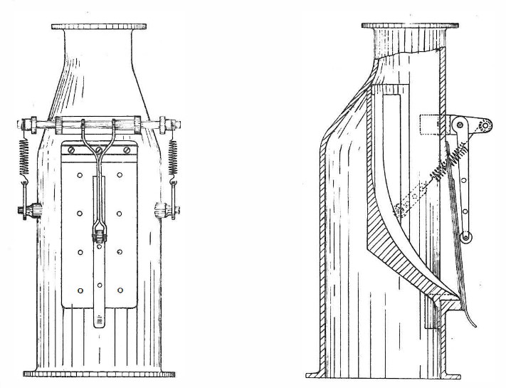
Fig. 2 - Flap Terminals
Fig. 3 - Flap Terminal In the outlying offices connected up. the messages can be inserted direct into the street tube by the receiving officer at the counter with no more trouble than that associated with the use of house tubes, a flap terminal again being used, and the delivery of the messages can be made direct lo the instrument room (as at the C.T.O.), or to the various sending out rooms, no auxiliary house tube system being required at the various offices. The special apparatus used has been i1wenled and designed in the Power Section of the Engineer-in-Chief's Office and erected by the London Engineering District. Compressor Room
Fig. 4 - Air Compressor From the Compressor Room the air is taken to pressure and vacuum headers in the Switch Room which in turn are connected through electrically controlled, pneumatically operated valves to the pneumatic tube switches. These Air Supply Valves, a bank of which can be seen in the illustration (Fig. 5), are operated by auxiliary Westinghouse valves. In these a solenoid causes a piston to open or close ports connected to an auxiliary air supply. This in turn moves a piston in the main valve against a spring opening ports which connect the tubes to the main air supply. On switching off, the valve body is connected to atmosphere and the spring returns the piston to the "off " position.
Fig. 5 - Pneumatic Switch Room In the case of tubes
working both "up" and "down," a second similar valve determines whether the
air supply is vacuum or pressure. The Pneumatic Switches are operated by means of magnetic
clutches connected through chains and gear wheels to line shafting The Pneumatic Switch consists of a fixed open cylindrical frame with top and bottom plates havi1ig orifices to which the street and house tubes are connected and also the air supply pipes (vacuum and/or pressure). Inside this frame is a rotating body consisting of three tubular sections welded at the lop and bottom to plates similar to those on the outside frame. Packing rings are inserted round the orifices to prevent leakage of air. When receiving, the carrier, which has been inserted in the street tube at the ''out'' office through a flap terminal, passes from the street tube into one of the tubular compartments of the switch, where it is held by a grid covering the vacuum supply pipe. As the earner rests against the grid it interrupts the flow of air, causing a considerable difference of pressure before and behind the carrier.
Fig. 6 - Pneumatic Switch Room - Control Board Small pipes are led from above and below the switch, transmitting these pressures to a Differential indicator. The Differential Indicator consists of a cast iron case divided into two compartments by a rubber diaphragm stiffened by aluminium discs proportioned to the pressures used. The movement of the diaphragm is transmitted by an axial pin to a pair of contacts, thus completing or opening an electrical circuit. The diaphragm is biassed by a spring against the difference of pressure due to the normal flow of air through the switch, and contact is only made when the difference of pressure is increased owing to the presence of the carrier in the switch. As soon as this contact is made, it completes a circuit through auxiliary plunger contacts on the switch and the magnetic clutch is energised and couples the switch to the shafting by a pinion and crown wheel. When the switch leaves its normal position the differential indicator ceases lo function and a retaining contact is provided to maintain the electrical circuit. When the switch has made one third of a revolution the carrier is brought into position to be blown into the house tube by the low pressure air from the centrifugal blowers, and the retaining contact is opened by means of a ramp fixed on the rim of the rotating part, leaving the switch ready to receive another carrier.
Fig. 7 - Centrifugal Blowers The switches are fitted with friction band brakes to minimise any variation in torque required by the various switches and to ensure stoppage at the correct points. A condenser is inserted to reduce sparking at the contacts. The carrier passes through the house tube and is blown through the flap terminal in the Tube Room. For sending from the War Office Centre the process is reversed, the carrier being drawn by vacuum from the flap terminal to the switch, which rotates and delivers the carrier to the street tube, whence it is discharged at the distant office through a flap terminal. Where there is likelihood of the carriers being discharged at excessive velocity a by-pass is fitted near the end of the tube releasing the pressure behind the carrier to atmosphere. Signal and Air Control Circuits
Fig. 8 - Driving motors In the case of long tubes this waste is greatly reduced owing to the frictional effect of the tube on the air, and it is only at rare intervals that there is no carrier in the tube. In these tubes the lime interval between the carriers would be too great if only one carrier were allowed to travel at a time and Signallers are placed to indicate the passage of a carrier at a certain distance from the sending point, after which another carrier may be inserted. Up till now, dependence has been placed on a timing control for loading long tubes, which is not satisfactory, as it does not prevent carrier after carrier being inserted if a carrier has stopped and so causing the tube to become jammed. With a definite space interval at the start and an open end trouble from this cause will not arise. On the trunk tubes to the C.T.O. this corresponds to a time interval of 10 to 15 seconds between the despatch of the carriers, which is ample, as there can be no delay in discharging the carrier from the tube, this being unrestricted by the flap terminal, which is not dependent on the attention of a tube attendant. The Signaller used is a Differential Indicator Signaller similar to the differential indicator used for operating the switches, but of a more sensitive type and with a greater range of adjustment with an external setting. The pressure pipes actuating the signaller are connected to the street tube at two points about 24 feet apart and the difference of pressure caused by a carrier traversing this section causes a contact to be made. The tubes are automatically blocked when sending from the War Office by means of a relay in the retaining contact circuit of the Pneumatic Switches.
Fig. 9 - Pneumatic Switch On shorter tubes, when arranged for receiving, the line is blocked by means of a press button at the distant station, and the same signal operates a Teleswitch which causes the air supply valve to open. The Teleswitch is a form of relay with contacts suitable for 200 volts, which are closed with the first current impulse, opened with the next, closed with the third and so on. When the carrier arrives in the Pneumatic Switch a relay is operated which clears the block signal and operates the Teleswitch again, cutting off the air.
Fig. 10 - Pneumatic Switch For sending on these tubes a similar arrangement was installed, but was not found to be quite satisfactory as no indication was given to the tube attendant that the air supply had actually been switched on. (In the case of a carrier being sent from an out office to the War Office it would not leave the attendant's hand until the vacuum was on the tube.) On these tubes therefore a modified form of starting switch has been installed; the handle is first pressed in, sending the block signal, and then the arm is brought over to the "on" position, when the air valve is switched on and the arm held over by a retaining electro magnet. When the carrier arrives at the distant office the attendant depresses his push button, clearing the block signal and releasing the switch arm, which is returned to the off position by a spring, cutting off the air supply.
Fig. 11 - Differential Indicator On tubes arranged for two-way working the signalling is automatic, but the control of the air supply is by hand. Automatic control of this by a further modification of the switch used when sending on short tubes, combined with the use of a Teleswitch for receiving, has been devised, but the wiring becomes very complicated and it is found that the arrangement used works well in practice. The current for the signal circuits is supplied from
rotary DC/DC converters (double-wound generators) at the War Office, power
leads being run to the outlying offices, replacing the batteries shown in
the illustration. The air supply valves and magnetic clutches me connected
to the public electricity supply
Fig. 12 - Control Diagram Costs In the first place, the introduction of tubes admits of the abolition of transmission of telegrams by wire and the saving on this account alone, amounting to some thousands of pounds per annum, having regard to the number of offices served by the tubes, was calculated to justify the expenditure, while the introduction of automatic working results in a further considerable saving. There are, however, other considerations. Although an individual telegram cannot perhaps be sent more quickly by tube than by wire, a number of messages can be conveyed in one carrier and the acceleration in transmission becomes very marked when large numbers of telegrams are handed in at one time, or where lengthy telegrams, or telegrams containing code or cypher, are required to be forwarded. The provision of tubes for newspapers in the same trench as the trunk tubes afforded a means of supplying the facilities at a lower charge than would have been the case if it had been necessary to open the ground for the purpose, and at the same time the revenue from these tubes allows for a certain margin of profit and can therefore be regarded partly as a set-off against the interest charges on the initial outlay. APPENDIX LIST OF OFFICES CONNECTED TO THE WAR OFFICE CENTRE
|
|||||||||||||||||||||||||||||||||||||||||||||||||||||||||||||||||||||
Last revised: January 05, 2024FM2 | |||||||||||||||||||||||||||||||||||||||||||||||||||||||||||||||||||||