SIGNALLING SYSTEM DC5


General Description
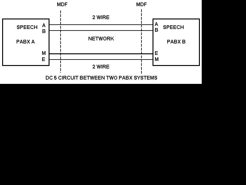
This signalling system is used for signalling between a PBX and co-sited equipment. The system operates over two discrete signalling wires which are electrically separated from the associated speech circuit. The two signalling wires are known as E&M. DC signals are sent on the M wire and are received on the E wire. Although the system is often referred to as E&M signalling it should be noted that it is not compatible with some other forms of E&M systems.

Note:
The transmission path may be 2 or 4 wires. 4 wire types have send and receive pairs and may be called 6 wire E&M.

dc5.gif (7863 bytes)


Transmission Requirements
The DC resistance limit for both signal wires is 25 ohms. The maximum current on the E&M wires must not exceed 25 ma.

Application of SSDC5-A
SSDC5A is mainly used for connection to remote equipment that is within a radius of 100 metres. Generally used as a universal method to connect to MUX equipment, signalling converters or signalling units.

Line conditions
The speech pair (pairs if 6 wire type) will terminate on a loop condition. The M wire will be disconnected when idle and earth when seized. The e wire has a –50v condition on it on idle.

To call the distant end an earth is presented to the m wire.

Testing a DC5 circuit
Check for –50v on the e wire from each end. Connect an earth on the m wire and this should seize the distant end.  The speech pairs should be tested for a 600 ohm (approx.) loop in both directions.  A thorough test is to back to back two circuits and dial through them to check correct operation.
Note: e and m wires are normally reversed!


BACK Home page BT/GPO Telephones Search the Site Glossary of Telecom Terminology Quick Find All Telephone Systems

Last revised: December 18, 2010

FM