|
 QWERTYPHONE
was a loud-speaking telephone with single or dual line access. Other features were,
advanced telephone, directory and autodialler PBX featurephone, calculator, message
terminal, modem for PC and manager/secretary system (optional on the dual line version). QWERTYPHONE
was a loud-speaking telephone with single or dual line access. Other features were,
advanced telephone, directory and autodialler PBX featurephone, calculator, message
terminal, modem for PC and manager/secretary system (optional on the dual line version).
A dot matrix or low cost thermal printer was available.
The equipment comprised, keyboard with 4 line 32 character LCD display, handset, modem,
RS232C PC port, printer port and telephony module.
Made by Rathdown Industries, Ascot.
ADDITIONAL INFORMATION
The QWERTYphone has been removed from the BT portfolio for some years but remained as a
maintainable item. It was completely withdrawn on February 1st 1993. They were not
recovered from customers premises. Customers with maintenance or rental agreements were
contacted and advised they could regard the instrument as their own and use it whilst it
remains serviceable. On no account were BT personnel to undertake any work on QWERTYphone.
From February 1st 1993, all QWERTYphones can be considered customer owned equipment and
disposal is their responsibility. However, the Royal National Institute for the Deaf
(RNID) is eager to maintain a stock of QWERTYphones for use by deaf people. The messaging
facility is extremely useful in these circumstances. As a gesture of goodwill, BT has
agreed to pass on any QWERTYphone equipment to the RNID who have trained personnel able to
repair faulty equipment.
British Telecommunications Engineering
Volume 5, Part 4, January 1987
QWERTYphone
A Low-Cost integrated Voice/Data Terminal
This article outlines the rationale behind British Telecom's
latest low-cost integrated voice/data terminal, the QWERTYphone, and
describes the design and development of the instrument.
INTRODUCTION
The QWERTYphone, a joint development between British Telecom's
Communications Terminal Products Group and Rathdown Industries, came onto
the market in November 1986. QWERTYphone is a full hands-free loudspeaking
telephone (LST), incorporating a large directory. In each of two secure
directories, 250 numbers, names and addresses can be stored. These
directories are then available at the press of a button. QWERTYphone is
programmed with the main system features of the most popular BT PABX systems
(including Monarch, Merlin DX and Regent). An integral V.21 modem gives
access to Telecom Gold and other dial-up electronic mail, databases and
display pager systems. Its built-in "memotyper" facility allows off-line
preparation of messages and, with the optional printer, doubles up as a
simple electronic typewriter. Also included are the functions of call timer,
calendar, clock and calculator. More advanced features include its ability
to be controlled by a personal computer either as a modem or as a
sophisticated computer-controlled telephone, and future upgrades include a
2-line manager/secretary option and faster modems. A complete list of
features is given in Appendix 1.
INITIAL CONCEPT
The initial concept of the QWERTYphone grew out of a study by BT's Human
Factors Division 1 at Martlesham Heath into directory usage. It was also
influenced by work on the Merlin Tonto 2 workstation which suggested that
the sort of telephony facilities provided by Tonto should be made available
at a much lower cost and in a more user-friendly manner. At this stage, the
product was known as the Directoryphone and as such its main feature was
seen as providing easy access to a large directory for autodialling.
Previous experience of autodialling systems led to the view that the best
way to access a directory entry was by name via a full typewriter-style
(QWERTY) keyboard rather than by some kind of shortcode or other reference
system. Therefore, the two major elements of the QWERTYphone hardware, the
keyboard and display, were justified by its base function.
A handset and telephony keypad were necessary to provide the integrated
function of a featurephone rather than an autodialler. It was at this point
that it was realised that, with the addition of a modem, all the components
of a simple low-cost terminal were present.
The next step was to put all these components together into a package that
would be attractive to the end user. Several sketches were commissioned to
evaluate possible shapes for the equipment, and the best two were made up
into wooden block models. In parallel with this activity, a computer
simulation of the equipment was built so that some of the user-interface
concepts could be tested.
CONCEPT TESTING
The wooden block models and computer simulation were taken to a company that
specialises in concept testing, a form of market research to test the
viability of completely new products. One of the main advantages of using
such a company was that its staff had no background in telephony and
therefore had no preconceived ideas or prejudices about the market.
The company prepared dummy sales literature and tested the products on
panels of prospective customers. Their research showed that with well
targeted marketing the product was viable but, significantly, showed an
acute price and timing sensitivity. That is, the product had to be designed
and manufactured under a specific price and be made available as soon as
possible. The company also came up with a suggested name for the product,
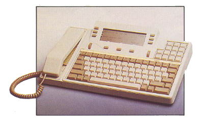
QWERTYphone, which has remained throughout its development and introduction
into service (see Fig. 1).
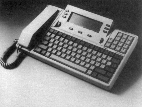
Fig. 1 - QWERTYphone
DISTRICT TESTING
The computer simulation was next taken on a tour of selected BT Districts
and shown to the business system managers and other interested parties. The
aim was to get comments from the Districts on the features and operation of
the product and to get some support before money was spent on development.
Response from the tour resulted in a development contract being placed.
Examples of the comments received from this tour and incorporated into
the development phase of the project were the inclusion of a full hands-free
LST version and another that supported two lines with manager/secretary type
facilities.
DEVELOPMENT
The development contract was placed with Rathdown Industries which had
already produced the computer simulation and had played a significant part
in specifying the user interface. The contract had a number of regular
outputs which began with a very early hardware version with no mouldings and
which went right through to final pre-production samples. This allowed the
software to be thoroughly tested and refined before the hardware was
finalised. The software was developed in a modular form with each particular
function being added separately, again to aid the software testing and
approval. Any faults or software bugs were logged, in addition to suggested
improvements to the user interface, and each new version of software was
thoroughly tested to ensure that all previously reported bugs had been
removed and would not recur.
Because of the severe price sensitivity highlighted during the concept
testing, the development contract included a fixed price for the final
product to prevent any changes being implemented which would increase its
final price. In addition, tight control was kept on the project's timescales
by using project planning techniques with well-defined mile-stones and fixed
outputs. This scheme worked very effectively and the project ran no more
than one month over schedule in 18 months.
The circuit (see Fig. 2) comprises five major components:-
-
the main processor board,
-
the telephone circuit board,
-
the telephone line interface circuit,
-
the display module, and
-
the serial interface board.
Main Processor Board
The main processor board contains an Hitachi 6303 micro-controller which has
on-chip memory, timer circuits and parallel and serial ports. This
controller drives the V.21 modem and multi-frequency (MF) dialer chips
directly in addition to accessing the program and directory memories.
One of the first major decisions of the design to be made was how to
implement the directory memory. The choice was seen as being between
battery-backed CMOS static random-access memory (RAM) or
electrically-programmable read-only memory (EPROM). The main considerations
were cost and integrity, or non-volatility, of the stored directories. As
the additional expense of providing any form of backup by using either tape
or disc was out of the question, and some concern was expressed over the
integrity of a battery-backed system, after careful consideration the EPROM
option was adopted.
The main disadvantage of using an EPROM is that each location can be written
to only once, so that once an entry is made into the directory, any
subsequent editing or deleting of the entry does not free memory space but,
in fact, uses up more. However, this disadvantage was discounted by careful
design of the user interface to encourage an entry to be edited before the
EPROM was programmed. By allowing a maximum of 250 entries to be addressed
at one time, a generous amount of editing space can be provided in one 16
Kbyte EPROM. Also, the provision of two directory sockets and a copy and
compact option in the directory menu means that, if all the space in a
directory is used up, then another directory module can be purchased and the
directory information copied into it, thereby making all the editing space
available again. From the information in the initial Human Factors report
and experience to date, it seems very unlikely that filling directories in
this way will be a problem to most users.
A directory module consists of an EPROM in a plastic carrier, which protects
the pins from being damaged on insertion or removal from the special socket,
and prevents damage from electrostatic discharges (ESDs). This system allows
directory modules to be removed from the QWERTYphone, carried in the pocket,
and plugged into other machines as required. Directories can be mass copied
by using a modified EPROM programmer.
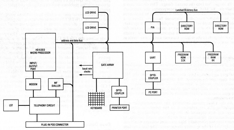
Fig. 2 - Block diagram of the QWERTYphone
Another major decision was the use of a gate array for keyboard decoding,
baud rate generation, printer port driving and other logic elements. This
gate array was designed by Rathdown Industries using the facilities provided
by SGS, and was a very critical part of the design. It functioned at the
second attempt well within its allowed design time.
Telephony Circuit
The telephony circuit was designed to meet the requirements of the British
Approvals Board for Telecommunications (BABT). As the equipment was to be
mains powered, the first decision was the placement of the barrier between
the 240V mains supply, the user accessible ports and the telephone network.
The usual method is to interface the non-speech sources to the network by
using a barrier transformer.
This limits the quality of the design of the transmission circuit and
adds the not inconsiderable cost of an extra transformer. Therefore, the
decision was taken to use the mains transformer as the principal barrier,
with a secondary barrier provided for the ports by using opto-couplers.
A transformer with two secondary windings isolated from one another was
designed specifically for the task. One winding supplied the telephone and
the main board, the other the isolated serial ports. The primary winding of
the transformer is separated from the rest of the equipment by careful
design of the transformer seating in the moulding. The whole of the
remainder of the equipment except for the peripheral side of the serial
ports is then referenced back to the telephone network. An interlock
designed into the moulding ensures that the telephone line is disconnected
before the equipment can be opened to access the directory modules.
The telephony circuit is based on a transmission integrated circuit (IC)
from Texas Instruments (TCM1715) which not only interfaces the speech
circuit to line, but also the MF dialer, LST and modem. It was decided at
an early stage in the development that the incremental cost of an LST
version was so small as to make the production and stock control of two
separate versions uneconomic. The circuit used for the LST was largely based
on a circuit developed by the Advanced Terminals Section of BT's Technical
Applications Department at Martlesham Heath, which assisted in its
integration into the overall design. This circuit uses a Motorola MC3418 IC
which incorporates the necessary amplifiers, attenuators, and control
functions to implement the half-duplex hands-free telephone function. There
is a microphone amplifier, a power amplifier for the speaker, transmit and
receive attenuators, a monitoring system for background sound level, and an
attenuation control system which responds to the relative transmit and
receive levels as well as the background level.
Telephone Line Interface
The different circuits to be interfaced to the telephone network are
selected by the microcontroller via an array of analogue switches. These are
also used to allow the MF tone generator to produce the various ring tones
via the loudspeaker, saving a tone-caller IC and a transducer. A selection
of six different ring tones is available to allow for personal choice or
differentiation of instruments in an open-plan environment.
As the whole circuit including the microcontroller and interfacing ICs are
referenced to the telephone network, great care was required in the design,
particularly of the loop-disconnect signalling and earth-loop recall
circuits, to ensure that the potentially high transient voltages would not
damage any of the sensitive components. The line interface parts of the
circuit are actually provided on a separate board, the telephone line
interface board, which is situated in a pull-out drawer-type pod external to
the main moulding. This effects the interlock with the part of the moulding
which opens to allow access to both the directory modules and the batteries
which provide power for the telephone in the event of a failure of the mains
supply. This pull-out pod connects to the main board by means of a 64-way
connector which, in addition to the telephone interface, carries the whole
bus system, thereby allowing other pods to be plugged in to provide enhanced
functions. Additional functions already available are a V.23 modem option
and a 2-line manager/secretary option.
The design of the speech transmission circuit is fairly standard, but
incorporates a new handset styled to match the instrument and designed to be
easy to assemble at a low cost. A low-cost electret microphone is used with
a plastic microphone holder that acoustically shapes the frequency response
thus saving on electronic filter components. The mechanical design is
greatly simplified by including a magnet in the handset to activate a reed
cradle-switch. This design is possible because the cradle-switch simply
provides a signal to the processor rather than having to carry line current
which would require a much more robust switch.
Display
The decision on what type of display would be used had to be taken early on
in the development of the QWERTYphone. As the main consideration was cost,
it was soon apparent that the best choice was a liquid-crystal display
(LCD).
The LCD adopted uses a custom display glass and proprietary driver ICs
housed in a custom module which formed an integral part of the top half of
the case moulding. This afforded a low-cost easy-to assemble solution.
Serial Interfaces
The QWERTYphone has two S5/8 serial ports provided with their own power
supply and isolated from the remainder of the circuitry by high-voltage opto-isolators.
The first of these ports is a serial printer port which operates at up to
9000 baud and is configurable for number of bits, parity and flow control.
These options are chosen from a screen menu and allow the QWERTYphone to be
used with a minimum of compatibility problems with virtually any available
serial printer.
The second serial port is a fully bi-directional serial port and allows the
QWERTYphone to operate in three different modes. The first of these modes is
a simple terminal mode so that the instrument can be used in a variety of
ways; for example as a terminal on a multi-user system. The second mode
allows the QWERTYphone to be used as a modem by any external computer. The
instrument is controlled by using the Hayes standard command set which is
implemented in terminal software on most popular personal computers. The
third mode of operation is called PC control.
This allows an external computer to control all the hardware of the
instrument and take back responses from the keyboard, modem and other
functions. One use of this feature is in end-of-line testing during
manufacture. A test set-up controlled by a computer brings up various
options on the LCD prompting the operator to press keys and read the
display. This enables the keyboard and display to be fully functionally
tested and enables the test set-up to exercise all the hardware and software
functions. Other uses of PC control mode are to provide for future upgrade
paths as described later.
Case Design
The physical design of the unit was constrained by the need
for a keyboard, display and handset with the minimum possible footprint (see
Fig. 3).

Fig. 3 - Keyboard layout of QWERTYphone
The keyboard was designed from scratch to provide a low-cost unit with a
good tactile response. This was achieved by using a touch-sensitive contact
mat topped with an elastomeric rubber pad and moulded keys to give the
correct weight and travel to the key action. The moulded key tops come in a
single assembly from the moulders and the whole keyboard can be printed with
the correct key legends in one action by using sublimation printing, an
advanced form of ink transfer system. This overcomes the quality assurance
problems associated with placing the right key in the right place.
The main moulding is in two halves, the bottom half houses most of the
circuitry and provides a safe housing for the transformer and shrouds the
mains cable connection. The top half of the moulding houses the display
module and keyboard. These are connected to the main circuit board by
separate connectors.
The handset rest area is a separate moulding which hinges forward to give
access to the directory modules and battery compartment. This moulding is
restrained as mentioned earlier by an interlock which ensures that the
telephone line is disconnected before access is given.
The line interface is situated in a removable pod at the rear of the bottom
moulding. This pod can be substituted with upgraded versions, and a larger
pod has been designed to accommodate the 2-line version and other options
that require more space than provided in the standard pod.
The serial ports are presented at the rear as S5/8 standard 8-pin DIN
sockets.
The handset is constructed of a two-piece moulding comprising front and
back. The two halves clip together and are secured by a single screw.
Internally, the construction of the handset is very simple. The receiver is
held in place with a form of high-integrity double-sided adhesive tape of
the type previously used in the automotive industry. The microphone clips
into its specially designed acoustic filter housing which, in turn, is
secured to the handset with double-sided adhesive tape. This tape is also
used to secure the cradleswitch magnet and an extra weight in the form of a
steel bar. The use of this tape rather than a complicated arrangement of
mechanical clips means that the handset is easy to put together and can be
produced at low cost.
ALPHA TRIAL
As mentioned previously, the development had several fixed
outputs. One of these outputs was a quantity of 100 samples with almost
finalised hardware so that the software could be tested with a wider
selection of users; this became the alpha trial. The samples were given to
potential users within BT, both technical and non-technical, and these users
asked to complete a form to report any software bugs, misoperations of the
unit or plain dislikes of the user interface. Over 250 of these forms were
returned and logged and any required changes were noted and passed on to the
software development team. Most bugs were cured by the next release of
software, and, as these were at approximately monthly intervals, new
software was tested as fast as it was written. Several significant changes
to the user interface were made at this stage as a result of suggestions by
the triallists.
Some of these later samples of the QWERTYphone were shown to a selection of
BT Districts to increase their awareness of the product and to elicit
further feedback. Examples of changes made as a result of this feedback
included the addition of a weight to the handset to improve its feel,
changes to the handset rest area to overcome complaints that the handset
could be knocked off its rest too easily, and a lightening of the keyboard
action to counter complaints
that it was too heavy.
FUTURE PLANS
Some of the future growth plans for the product have already been mentioned.
The first of these to appear is called the keyboard interface adaptor. This
extra piece of hardware plugs into the serial port of the QWERTYphone and
comes in several versions - currently an IBM PC version and an Apple
Macintosh version. The adapter plugs into the keyboard connector and the
serial port of the relevant computer (see Fig. 4). Pressing the PC key turns
the QWERTYphone
into a combined keyboard and modem, while pressing the exit key returns the
QWERTYphone to its native mode of a feature telephone. This combination
works with all the standard software packages on these computers and new
software is now under development by leading software houses to exploit the
more advanced features available for specific applications such as
Tele-selling and Tele-marketing.
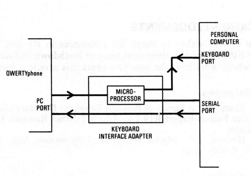
Fig. 4 - Connection of QWERTYphone to a personal computer as a keyboard and
modem
The second upgrade to appear will be the 2-line manager/secretary option.
This product expands QWERTYphone's voice and data capabilities to allow two
QWERTYphones to control two telephone lines, either PABX or direct exchange
lines, as a fully featured planset (see Fig. 5). A full handsfree intercom
connection is provided independent of the telephone lines and can be used
without interfering with any calls in progress. Pressing the boss/sec key on
the
QWERTYphone will give a full screen display of the status of the lines and
the options available. Calls can be made and received on either line, held,
transferred or three-party conferences set up.
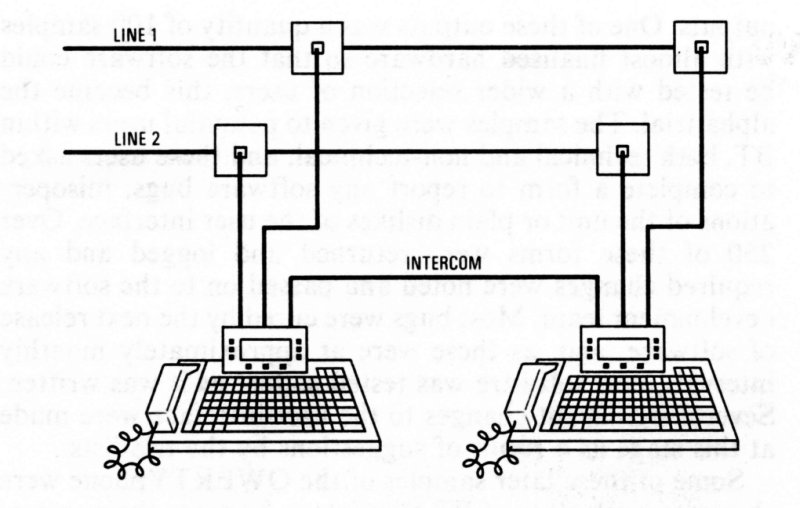
Fig. 5 - Connection of two-line QWERTYphone as a manager/secretary system
Other upgrades under development include V.23 and V.22 modem options. Other
suggested uses of the add-on pod system, including a card-wipe option and a
Telex interface, are under consideration.
There is scope for marketing the product internationally, but this will
entail development of new line interfaces and, in some instances, new
language versions. Interest has already been shown in Italy, West Germany,
Canada and the USA.
APPENDIX 1
QWERTYphone Product Features
Advanced Telephone
Pulse and/or tone dialling, earth-loop or timed-break recall, choice of six
ringing tones, last number redial, call timer, clock calendar, batteries
provide basic telephony and protect configuration details if mains power
fails (directories in non-volatile store are not dependent on mains or
battery power).
Directory and Autodialler
Capacity for 250 entries in non-volatile directory module, character-string
searching over all parts of each entry, autodialling
from directory, modules can be copied for use in other QWERTYphones, socket
for second (optional) directory module.
Password Security
A programmed password can be used to prevent unauthorised access to the
information stored in the QWERTYphone. Local security prevents the
QWERTYphone from being used other than as a simple telephone; that is, by
lifting the handset.
PBX Featurephone
For BT PBXs: DX, Monarch/IT440, Viceroy, Kinsman and Regent (four special
commands enable features for other PBXs to be stored in the directory), it
provides single key access for the PBX's most commonly used features.
Function Keys
Ten function keys give instant access to the QWERTYphone's features; seven
of them are user programmable.
Screen Keys
Nine keys associated with the screen change their function according to the
facilities in use; the functions currently in operation are indicated on the
screen.
Calculator
Four functions - available as screen key options plus (with printer option)
printing calculator.
Messaging Terminal
Sends short text messages to other QWERTYphones.
Receives text messages from other QWERTYphones, Merlin Tonto and M2105
terminals or any terminal with a V.21 modem, interactive messaging is
available between QWERTYphones allowing text-based conversations for
speech-impaired users.
Remote searching of directories in other QWERTYphones (users who wish their
directories to remain confidential can lock
them).
Memotyper
Produces and edits memos line by line with the optional printer; text is
also stored in a buffer for reprinting or later transmission
via the internal modem or RS232 serial port, line length options of 32, 40,
69 or 80 characters available to accommodate other
printers. Used with a printer it becomes a simple electronic typewriter
Computer Terminal
Terminal with simple glass teletype emulation, can access main-frame
computers via the integral modem or via the RS232 serial
port and an external modem, host or DOV unit, configurable for speed, word
length, number of stop bits and flow control,
text may be prepared off-line by using memotyper, and logon details may be
stored and sent by using the programmable function keys.
Modem for PC
The integral modem can be controlled by a personal computer connected to the
serial port using Hayes smartmodem control codes.
Manager/Secretary System (Option)
Two QWERTYphones working together as a plans system, one or two lines, full
intercom, hold, transfer, conference, do not disturb, and line status
display.
Qwertyphone Customer notes -
TGN0035
|