| |||||||
|
This is a PABX produced by the Relay Automatic Telephone Company (R.A.T. or RAT Co.). Invented in 1912 by G. A. Betulander and N. G. Palmgreen, the system consisted of relays only. These two engineers owned their own company in Sweden called Nya Autotelefon Betulander. Established as the Betulander Automatic Telephone Company by Marconi's Wireless Telegraph Co. Ltd in 1913 the company was later renamed as the Relay Automatic Telephone Company. The relay systems were developed from that devised by Gotthief Angarius Betulander, who was an engineer in the Swedish Post Office. It is thought that during the period of the First World War there was no development of the system. In 1920 the system was exhibited at the Machine Tool and Engineering Exhibition at Olympia with automatic telephones for business premises. This system, although on exhibition, also supplied the telephone service for the administration offices, the Indian Empire and many other exhibits. July 1922 saw the first 'relay' automatic exchange for the public telephone service in the UK opened in July at Fleetwood, Lancashire by the Relay Automatic Telephone Co. This was to be the only public RAT Co. exchange installed in the UK. RAT systems continued to be installed as P.A.B.X. systems, the first being at the Liverpool Courier in January 1922. This system was equipped initially with 50 extensions which could be expanded to 80 extensions. The General Post Office, in 1922, adopted the Strowger system as its standard automatic exchange for the UK network. The relay system was considered better suited to small private automatic branch exchanges - the first installed for the Post Office was at Debenhams in Wigmore Street, London, in 1923. The systems were produced in sizes ranging from 6 to 10,0000 extensions. Three types were available: PAX (internal only), PABX (internal and external) and Minor (6+24 only). The company made 24 volt and 32 volt systems. The 32v PABX is installed where the number of trunks (AB feeds) will exceed 17, or 240 lines, and in cases where the manual switchboard equipment includes a multiple. The manual switchboard will still operate on 24 volts, obtained by the use of counter E.M.F. cells. Subscribers groups contain 10 extension line equipments numbered 0 - 9 and all are mounted in one case. A 400 line PABX, for example, would contain 40 subscriber units. The systems could support: Executive Intrusion, Conference calls, Dictation circuits and Code calling. The works were at Relay House, Streatham Hill, London, SW2. The Great Western Railway also used these PBX's and a PAX, the Model 10, was known to have been installed at Newton Abbot (taken from a diagram dated 1947). In 1926, A RAT Co. P.A.B.X. installed in the basement of a Lancashire Mill was flooded to a height of 4 feet. The water was pumped out, leaving 3 inches of mud on the floor. On removal of the relay covers the apparatus was found to be smothered with a film of slime and green rubbish. The apparatus was cleaned with the use of a fire hose, the flooded batteries drained and refilled and the moisture removed with vacuum cleaners switched to "blow". Out of 600 relays, 8 had to be replaced. In 1927 the London & North Eastern Railway (LNER), used RAT PBX's. Some 600 lines were installed, with about 10,000 relays and a quarter of a million contacts. Other UK customers included Lloyds Bank, Edward Boustead & Co. (Leadenhall Street, London, EC3), the Royal Naval College (Greenwich), the South London Hospital for Women (Clapham Common), the Chelsea Hospital for Women, the Educational Supply Association, the London Hospital, J. G. Kincaid (Greenock), Shell Mex, Barclays Bank (London) and many others. The Relay Automatic Telephone Co. also sold telephones, but there is no information to support if they were produced from parts or just purchased ready made from other manufacturers. Click here for some telephone pictures. In 1930 the RAT Co. entered into an arrangement with the Sterling telephone company, where the factory at Streatham Hill would manufacture both systems and telephones. 1930 also saw Siemens Brothers take over the maintenance work of the RAT systems sometime later the company products were also taken over and were then referred to as Siemens Relay No. 1 (24 volt) and Relay No. 2 (32 volt) systems. Principles of the RAT 24 volt system - Engineering Instruction - Telephones PBX C1501. POEEJ Article on RAT operation
Drawings
Model 10 - Technical description.
There is no definitive list of types and model numbers, but below are a list
of known products:- General Overview SECTION 1 - GENERAL (1) Introduction The 24-volt system provides for exchanges of 240 lines or fewer, while larger exchanges are provided for by a 32-volt system. The following description refers to the 24-volt system.. . Although. the Relay system works on principles different from those of the step-by-step systems now standard for public exchanges, there is no difference in the manner of making calls, and a subscriber accustomed to the step-by-step system can proceed to make calls on a Relay P.A.B.X. exactly as on the public system. The standard dial is provided and is used as described in Part 1 of T .I. XXV. As its name implies, the Relay system effects all switching operations solely by the use of relays and does not employ mechanical switches. The apparatus racks, instead of carrying selectors, are equipped with relays assembled in groups under protecting metal covers. The separate relay groups constitute individual circuits or groups of similar circuits. The names given to the principal relay groups employed in establishing a connection and the functions performed by them are outlined below :-- (2) DEFINITIONSSubscribers' Unit - The apparatus individual to five subscribers' lines is assembled together and constitutes a Subscribers' Unit. This performs functions similar to those of a; line switch in step-by-step systems, in that it effects selection of a free channel to common apparatus which responds to the dialled impulses. Inward calls are also passed via the Subscribers' Unit. AB Feed - This is a group of relays which performs the function of an operator's cord circuit. It does not perform switching operations. The AB Feed provides the calling and called party with speaking current and holds the connection during conversation. Marker - This is a relay group which establishes the connection between the called line and that particular AB Feed which is taken into use by the calling subscriber. There is only one Marker in the exchange and it operates under control from a Recorder. Recorder - This is a group of relays which receives and counts the caller's dialled impulses. When the called number has been completely dialled, the Recorder takes into use the Marker and causes it to select the called line. Recorder Connector - Incorporated in each AB Feed is a relay group which serves to connect the Feed with a Recorder preparatory to the commencement of dialling. This group may be likened to an operator's listening key, which associates a cord circuit with the operator's head set while the demand for the call is being passed.
(3) Fundamental Principles The general construction of P.A.B.X.'s of these sizes is described in paragraphs 92-120. In order that two subscribers shall be able to converse, they must be connected respectively to the answering and calling sides of the same AB Feed.
Taken from a paper read at the IPOEE in
January 1932 RAT Co. 24v and 32v PABX's
Siemens Relay No. The whole of the operations are dealt with by relay groups, and the by-path principle of operation is employed. Such a principle is essential, or the number of relays involved would be excessive. The relays are made up into groups which are necessary to perform the functions of storing, routing and connecting the calls to their various destinations. Operation
Schematic diagram The "out-trunk" is associated with an A.B. Feed which forms part of the out-trunk, and contains the transmission elements, dialling tone, busy and ringing connections. The A.B. Feed so seized searches for a free Recorder, which, when found, is connected to the A.B. Feed via a Recorder Connector. At this stage the caller hears dial tone and commences to dial.The dialled impulses are repeated into the Recorder, which stores them until all have been received. The Recorder then "marks out" and, with the aid of a common relay group termed a "Marker," sets up a connection between the called extension line and the A.B. Feed, upon which the caller is waiting. The "Marker" can only be taken into use by one Recorder at a time. The connection is set up over an "intrunk" via a "Trunk Connecting" Group. When a connection is established between the two extensions, the Recorder and Marker, which comprise the by-path circuits, are released and become available to other callers. If the called extension is engaged, then no connection is set up between the A.B. Feed and the called extension, and the A.B. Feed will return busy tone to the caller.Ten extension line equipments, in two units of five lines each, form one group, and are contained in a group case.Four A.B. Feeds and a Trunk Connecting Group of corresponding size, are mounted in another group case which is wired for a maximum capacity of six A.B. Feeds. Each Recorder is assembled into separate and smaller group cases.Similar equipment is employed in the 32v system. The whole equipment is therefore in unit form, and so many of each type of relay group may be assembled on suitable racks to form a P.A.B.X. of any desired size. The group cases are cabled to terminal assemblies located above each bay, and may be cross-connected to equipment mounted in the same bay by straps, and to equipment in other bays by tie cables.The system is very quiet in its operation, and can, therefore be installed in the room occupied by the manual board.In the author's opinion it is an ideal P.A.B.X. system, being capable of extension to 240 lines in the case of the 24v system, and from 300 lines indefinitely in the case of the 32v system.Standard P.G. and other alarms are provided and direct access, tie line and bothway junction working on an automatic basis may be provided to Post Office specification by the addition of suitable relay groups and with the minimum of alteration to existing apparatus.The 24 volt system will operate satisfactorily over a voltage range of 22-26 volts.The 32 volt system operates over a voltage range of from 28-34 volts.
'Relay Minor Systems' The 'Relay' Minor possesses all the reliability and absolute secrecy of the larger type. It is just as simple, just as efficient, and it gives the same constant day and night service entirely independent of human operators. The 'Minor' System is designed for private service only, and to accommodate offices and works that require anything from 6 to 24 lines. The smaller sizes can be added to quite easily from time to time until the maximum of 24 lines is reached. The 'Minor' Exchange is built up entirely of simple relays, and, as in other 'Relay' Installations, the absence of cumbersome mechanical switches assures its perfect reliability and reduces its maintenance cost to negligible proportions. The Switchboard is arranged to stand close to a wall, the apparatus being hinged so that complete access back and front is provided whenever necessary. The floor space occupied is approximately 1ft. by 2ft., and the exchange is 3ft. 6in. high for 6 and 12 line installations, the height increasing to 5ft. 3in. for the 18 and 24 line sizes. The whole of the electrical energy required is supplied by a battery of primary cells, which will, without attention, run an exchange from six to twelve months. The usual set of accumulators, power board and charging arrangements are entirely dispensed with. The use of primary batteries is made possible by the low current consumption, and by the very wide variation in voltage over which the exchange will work satisfactorily. The 'Minor' employs a novel method of number selection; the ordinary automatic dial has been replaced by a rotatable disk which is wound round until the required number is seen through the window of the instrument (see illustration), and then the key at side is momentarily depressed. This method of selection is extraordinarily rapid, the actual connection being made in a fraction of a second. The ringing is automatic, the called party's bell continuing to ring until he answers or the caller abandons the call. The conversation is absolutely secret, there is no risk of overhearing, and a third party cannot intrude upon an engaged line. At the conclusion of conversation either party hanging up immediately restores all apparatus to normal. Should it be desired to call the same number again, it is only necessary to lift the telephone off the rest and push the button. Another special feature of the system is that receivers accidentally left off do not engage any of the automatic exchange apparatus nor cause any current to be consumed.
Several special features have been incorporated in the design of the 'Minor'
System:- (2) SECRETARIAL CONTROL. Two instruments can be connected to one line so that calls may be originated from either, but incoming calls are received on one only. The call can be picked up on the other instrument if required. The increased cost here is merely that of the second telephone. (3) PRIORITY SERVICE (Executive's right-of-way). Included as a standard feature is the special facility for a Master Station always to obtain the desired connection if the wanted line be engaged. This means that ordinarily all conversations are secret, but that the Master Station has the power to tap all engaged lines; if an absolutely secret system is required, the master facility may be dispensed with. (4) CODE CALL (Round Call, General Call). By installing the necessary hooters, an efficient system for locating wanted persons in or about the premises, but away from their telephones, may be provided. Every telephone is equipped with a key for sending out the codes, and upon recognising his code, the wanted party can immediately reply to the caller from any telephone. The 'Relay' Minor is entirely unique. It is automatic in every sense of the word. Nothing could be quicker, simpler or more reliable. The switchboard needs no oiling, no cleaning, and no attention to keep it in working order. It possesses all the advantages of the 'Relay' P.A.X. at a lower cost to those whose automatic requirements will not exceed 24 lines. For the smaller organisation it is the ideal system.
Relax Minor for Ships
RELAY AUTOMATIC TELEPHONE COMPANY (RATCo) EXCHANGES IN THE LONDON AREA During the 1920s the Relay Automatic Telephone Company (RATCo for short) achieved some success with its system for PAX and PABX installations. One of the first was in December 1923 at the British Empire Exhibition (Wembley) where a system with in excess of 200 lines linked the pavilions of the various dominions and colonies with each other and the exhibition headquarters. The actual apparatus was one of the public exhibits. The company made great play of the speed of connection ('through in a second') and the simplicity of the equipment. One customer taken in by this was Lloyds Bank, who had a large PAX system using P.O. private wires to interconnect its headquarters with most branches. The head office latterly used a Siemens 17 PAX but the bank branches were equipped with RATCo PAX's. Other customers included Edward Boustead & Co. of Leadenhall Street, EC3, the Royal Naval College, Greenwich, the South London Hospital for Women, Clapham Common, the Chelsea Hospital for Women, the Educational Supply Association, the London Hospital and others. There was just one public exchange with this equipment, at Fleetwood (Lancs.). By far the largest installation in London, and by all account in the whole country, was that of the London & North Eastern Railway (LNER), provided in 1927. Some 600 lines were installed, with about 10,000 relays and a quarter of a million contacts. Outgoing calls to the public network were connected via a manual switchboard because of the Post Office's insistence (at that time) on no electrical contact between their exchanges and others. Four relay exchanges were installed, with the following numbering scheme:
Kings Cross exchange was the only one of these that I saw. It closed about 1973 and was located on the top floor of the West Side offices, alongside Platform 8 (platform 10 in those days before renumbering). Its physical location was on the first floor, about halfway along the platform from the barrier. Reg Freer, a rather resourceful technician, had his office/mess room opposite and had wired up a contact on the door to that corridor so that a discreet buzzer sounded whenever anyone came up the stairs to visit the exchange. The equipment was too bulky to save; there were a large number of steel-cased cabinets, all painted black and a manual switchboard of about four positions in the room next door. As mentioned, all external calls had to go through the operator; you could not dial 9 for an outside line. Sam Hallas recalls one of the technicians telling him the key switches in the switchboard were so worn that the points on one side of the contacts had worn holes right through the plates on the opposite contacts, making connection rather intermittent! The RATCo exchange on the station at coexisted with a PABX3 in the divisional offices at Great Northern House, just down Euston Road. This was because the RATCo didn't have sufficient capacity to handle GN House as well. One relic of the RATCo survived well into the 1970s and perhaps does even now. The 'Kings Cross Dining Club' (canteen) was in the last building on the top floor of East Side Offices and just over the entrance door was a Bellset No. 1 with a gold 'Relay System' transfer on the front. I always wanted to snaffle this but in truth it was in very poor condition. In common with most other relay systems, the equipment at Kings Cross did not return dial tone. This was a frequent source of fault reports to the technicians, who took pleasure in telling their calls that this was quite correct - there was no dial tone because the system was so fast it didn't need one!
Pictures
24 volt - 6 trunks and 20 extensions (Picture dated 1939)
40 line system but only equipped with 30 lines
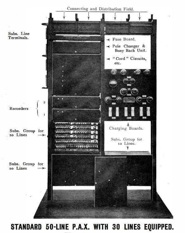
50 line system but only equipped with 30 lines
50 line system but only equipped with 30 lines
70 line system but only equipped with 60 lines
24 volt - 300/500 system
Alternative Group
Alternative Group rack
24 volt - Subs Group and Recorder
Subscriber Group Case
Subscriber Group rear view
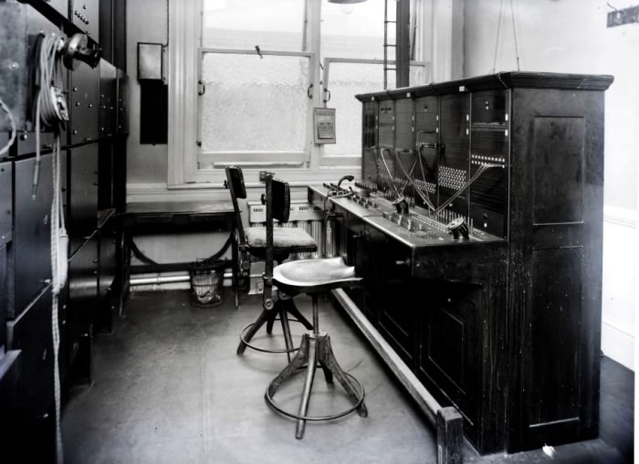
Switchboard (Picture dated 1925)
Switchboard at Henry Gardner, 2 Metal Exchange, EC3
Ringing Machine, Rat No. 16 (Mk 2)
Ringing Machine, Rat Type M
RATco Relays
MDF with Tester No. 64
Advert (Dated 1917)
|
|||||||
Last revised: November 24, 2025FM |