RELAY 3000 TYPE | |||||||||||||||||||||||||||||
|
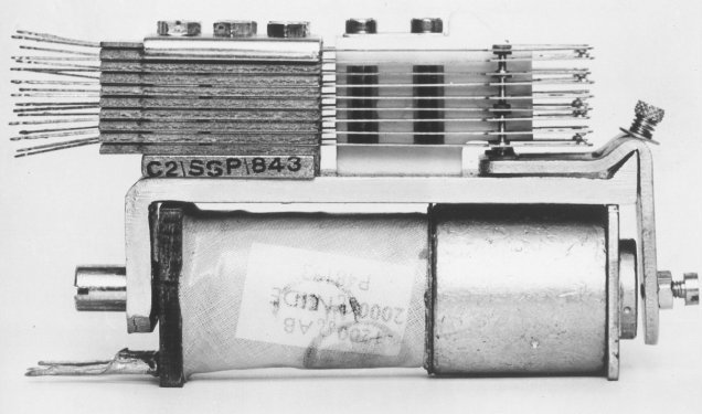
THE POST OFFICE 3000 TYPE RELAY GENERAL
Code Labels Springs and tag numbering The essential components of the relay are as follows:-
Main parts of the 3000 Type Relay
ESSENTIAL FEATURES OF THE RELAY The resistance of the magnetic circuit to the creation of flux is known as the reluctance and to ensure a low reluctance the following steps are taken:-
The Coil The ends are brought out on two, four or five tags. The range of winding resistance is from 0.1 ohm to 42,000 ohms, but with a maximum of 10,000 ohms when a copper slug is fitted over either end of the core to give slow operation or release. When high impedance is required, as in transmission battery-feed bridge relays, the core is enclosed in nickel-iron sleeves. The Spring-set
The four types of contact unit in general use and the associated diagram symbols are shown Figure 1 below:-
'MAKE' CONTACT UNIT (M) is a combination of two contacts which make connexion when the armature operates. 'BREAK' CONTACT UNIT (B) is a combination of two contacts which break connexion when the armature operates. 'CHANGE-OVER' CONTACT UNIT (C) is a combination of three contacts in which a connexion is broken between two contacts, and a connexion is made between one of these two and the third contact, when the relay is operated. There is normally a short period, known as the transit time, between the break and make actions. 'MAKE-BEFORE-BREAK' CONTACT UNIT (K) is a change-over unit
in which the second connexion is made before the first is broken.
Where palladium contacts are fitted the springs have semi-circular notch while platinum have a vee notch. (see figure 4).
As a further safeguard, relays should be mounted with the springs in
the vertical plane, to minimise the possibility of dust settling on the
contacts. ARMATURES The requisite residual gap is ensured by means of a fixed stud or adjustable screw with lock-nut and is generally within the limits of 4 to 20 mils. GEC advise that fixed stud residuals are manufactured in lengths of 4, 6, 12 or 20 mils (1 mil = 0001 in. = 00254 mm.). Isthmus Armature
Relay with Isthmus Armature SLUGGED RELAYS The Characteristics can be:-
The amount of delay depends on the length of the slug. Slugs can
come in lengths of 0.5", 1" and 1.5" and are factory fitted.
Relay with an Armature end slug
HIGH IMPEDANCE RELAYS LABELS ATTACHED TO CORE CHEEK The labels are coloured white, green or red, the colour indicating the type of adjustments to be applied to the relay. The white and green labelled relays have standard adjustments applied to them. The white label indicates that the relay has springs which are 14 mils thick, the green labelled relay has 12 mil thick springs. The red label indicates that the relay is a special one, and that adjustments applied to it must be strictly in accordance with the relay adjustment card.
METHODS OF INDICATING ADJUSTABLE RESIDUALS Residual values of white and green label relays are always shown on their respective code labels. The following differences in markings on relays with respect to adjustable residuals apply. (The code number used is for illustration purposes only):-
Taken from the GPO London Telecommunications Engineering Training Centre Note for Students and GEC documentation
|
|||||||||||||||||||||||||||||
Last revised: March 30, 2023FM | |||||||||||||||||||||||||||||


