|
Before the GPO started to number relays, they were either
described or lettered.
This page shows the Post Office Standard Relay. These
were mounted on a wooden base which also had the terminals fitted.
Later a square base was introduced which could be fitted with spring clips
and then plugged into a mounting. These were mainly used on telegraph
circuits.
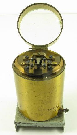
The relays were enclosed in a tin cover with a glass,
opening, window on the top. This allowed visual inspection of the
contact points when adjust via the Vernier screw on the side of the casing.
| Relay, Post Office Standard A For general
telegraph purposes, except Wheatstone circuits.
Coil resistances of 200ohms each.
Superseded by the Post Office Standard Relay B.
|

|
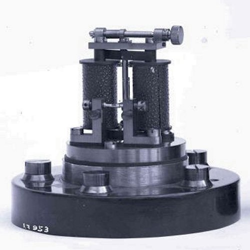
| Relay, Post Office Standard B For Baudot sets and repeaters boards on which spring
contact clips are used.
Coil resistances of 100ohms each.
Supersedes the Post Office Standard Relay A.
Standard B with rectangular base
Originally fitted with a 6 terminal
rectangular base of dimensions 4.75" x 3.75". Later supplies
were fitted with a 7 terminal base. These relays were used
when fitted on boards with spring contact clips.
|
|
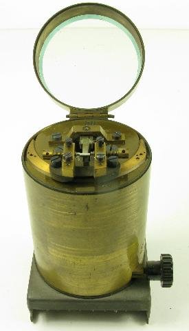
| Relay, Post Office Standard BN For Panels,
Telegraph. Mounted on a , For jacking-in to Baseboards, No. 26.
|
|
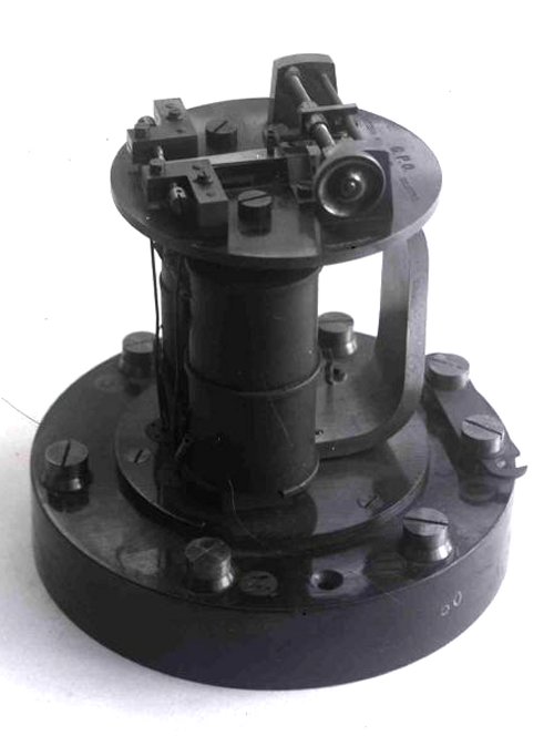
| Relay, Post Office Standard C
|
|
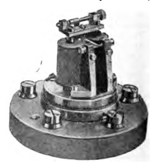
| Relay, Post Office Standard
D This was used as a translating relay on the London
Switching System.
Total resistance is 200ohms.
|
|
| Relay, Post Office Standard G Used with Wheatstone receivers.
Originally 9 terminals (TG504) but later supplies were fitted
with 10 terminals (TG261).
Coil resistances are 100ohms each.
Diagrams - TG504 and TG261.
The base is a called a Baseboard No. 11.
Supersedes the Gulstad relay.
|

|
| Relay, Post Office Standard GN For Panels,
Telegraph, For jacking-in to Baseboards, No. 26.
|
|
| Relay, Post Office Standard H 12 terminal
change-over relay with multiple windings on each bobbin.
This was a double differential polarised relay with vibrating
coils.
Used for double wire working on underground circuits.
The base is fitted with contact plates.
Coil resistances:-
Lines coils - 65+65+65+65ohms.
Vibrating coils - 100+100ohms.
Diagrams - TG416 and TG471.
|
|
| Relay, Post Office Standard HN For Panels,
Telegraph, For jacking-in to Baseboards, No. 26.
Base fits a Jack No. 48.
|
|
| Relay, P1 B
|
 |
Pictures

Relay ready to be inserted into mounting (Baseboard No. 12)

Relay inserted into mounting
|