TELECOMMUNICATIONS INSTRUCTION
C MARKETING - INSTALLATION
3 INTERNAL
M 0030SENDER No. 2 (RAPIDIAL)
Description, Installation and Maintenance
General
 This
Instruction describes the Sender No. 2 (known as Rapidial), which enables subscribers
connected to automatic exchanges to call other subscribers without the necessity for
remembering or dialling the telephone numbers. To call subscribers other than those
catered for on the Sender No. 2 the normal telephone dial is used. The Sender No. 2 is known
by its makers, Thomas A. Edison Industries of New jersey, as a Rapidial. As only a small
quantity of senders are available they are under 'E' control and are only issued to
subscribers specially selected by the Headquarters Administration. This
Instruction describes the Sender No. 2 (known as Rapidial), which enables subscribers
connected to automatic exchanges to call other subscribers without the necessity for
remembering or dialling the telephone numbers. To call subscribers other than those
catered for on the Sender No. 2 the normal telephone dial is used. The Sender No. 2 is known
by its makers, Thomas A. Edison Industries of New jersey, as a Rapidial. As only a small
quantity of senders are available they are under 'E' control and are only issued to
subscribers specially selected by the Headquarters Administration.
Description
The sender is a 'repertory dialler' with a magnetic tape memory and is used in conjunction
with a normal telephone. Telephone numbers are recorded on magnetic tape in the form of
v.f. pulses, the lengths of which are determined by the digits. When a recorded digit is
to be transmitted the v.f. pulse on the tape is amplified and rectified and the d.c. pulse
so produced used to operate a magnetic clutch. This clutch engages a pulsing cam with the
shaft of a synchronous motor and loop-disconnect pulses are produced by a spring-set
operated by the cam. The number of pulses produced depends upon the length of time the
magnetic clutch is operated, which in turn depends upon the length of the v.f. pulse
recorded on the tape. Two pairs of cam-controlled off-normal springs are operated during
pulsing and these short circuit the telephone during sending. Any tones encountered during
the setting up of a call are not heard until the off-normal springs restore.
The magnetic
tape, which is approximately 80in long x 5in wide, is stored on a pair of rollers. The
tape is scanned transversely and a maximum of 290 telephone numbers may be recorded. The
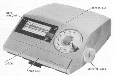
tape is positioned for recording or sending by rotating the selector knob on the
right-hand side of the sender in either direction to bring the required track beneath the
record/replay head, the tape being transferred from one roller to the other. Each track is
approximately half an inch wide and can accommodate a 22-second recording, e.g. 14 digits
'7' with inter-digital pauses. One track is used for each recorded telephone number.
Synchronised with the magnetic tape is a writing tape which is divided into alphabetical
sections so forming a name directory on which the recorded numbers may be written in
pencil.
The sender is mounted on a metal baseplate with four rubber feet and has a beige-coloured
plastic cover. The overall dimensions are approximately 9.1in wide x 12in deep x 4.1in
high.
The power unit is operated from a 200-250v a.c. mains supply and the output voltages will
be in the range 17-29v a.c. depending upon the voltage of the mains supply. The power unit
is designed for wall mounting and has a grey-coloured metal cover secured by two
self-tapping screws.
The overall dimensions of the unit are approximately 4in wide x 4.3in
deep x 3in high.
The sender and power unit are supplied together complete with cords but a Block, Terminal,
No. 20/8 should be requisitioned separately. A 3-pin mains plug will be required for the
power unit.
To record a number:-
(a) Rotate the selector knob until the desired space on the alphabetical index appears
between the two black lines on the plastic window.
(b) Move the latch on the record bar to the right and slide the record bar down until
it locks in the operated position, uncovering the writing tape.
(c) Write on the writing tape, using erasable pencil, the name and telephone number to
be recorded.
(d) Dial the desired number into the sender by means of its special dial. A standard
inter-digital pause is automatically provided between digits.
(e) Restore the record bar to normal by moving the latch to the left.
The telephone number has now been recorded.
Long inter-digital pause
The mechanism automatically provides an inter-digital pause of 800- 850 ms and under all
ordinary circumstances this is adequate. If a long inter-digital pause is required this
may be recorded by using the small red press-button which is visible when the record bar
has been lowered. The button should be pressed after the appropriate digit has been
dialled and the sender has come to rest; this increases the pause to 2100 ms. One example
of the use of this facility is at P.A.B.X.s where the digit 9 is used to gain access to
the public exchange and additional time must be allowed for the main exchange equipment to
be seized. Only one long inter-digital pause may be used per telephone number. The special
dial on the sender is automatically locked during the time that an inter-digital pause is
being recorded and is unlocked when the mechanism is prepared to receive the next digit.
To erase a recorded number
(a) Rotate the selector knob until the number to be erased appears between the two black
lines on the plastic window.
(b) Move the latch on the record bar to the right and slide the record bar down until it
locks in the operated position, uncovering the writing tape.
(c) Erase the writing on the writing tape with an India-rubber eraser.
(d) Move the latch on the record bar to the left and allow the record bar to restore to
normal.
The telephone number has now been erased from the magnetic tape memory.
To make a call
(a) Rotate the selector knob until the desired name and/or number appears between the two
black lines on the plastic window.
(b) Pick up the telephone handset and listen for dial tone.
(c) Depress and release the start bar which is situated on the front of the sender.
The sender will now automatically send the recorded telephone number and then disconnect
itself from the line leaving the call held by the telephone.
To make a call to a number not recorded, the dial on the telephone is used to dial numbers
in the ordinary way, the dial on the sender is only used for recording.
Installation
(a) Remove the two round-head screws from the sides of the power unit and remove the
cover. Mount the power unit, using three No 8 wood screws, within 6 inches of a 200-250v a.c. 3-pin power supply point. Connect a 3 pin plug to the power unit mains cord. If a
fused plug is used, the fuse rating must be 2 amp.
A 3 pin plug must be used and the green wire must be connected to the earth terminal.
(b) Locate the sender in a convenient position near the telephone but avoid placing it
near electric typewriters or other similar electrical devices.
Connect the power supply cord to the power unit as follows:-
Pass the cord under the small loop in the metal saddle and under the terminal strip.
Terminate the conductors on the terminals in accordance with the marked colours. Should it
be necessary to extend the length of the power supply cord between the power unit and the
sender use Cable, P.V.C. No. 1, 8 Wire, Grey. Each twisted pair in the P.V.C. cable should
be used as a single conductor and a Block, Terminal, No. 2014 used to join the P.V.C.
cable to the power supply cord provided with the sender. The length of extra cable
provided should not exceed 17 feet. Replace the power unit cover.
(c) The sender may be connected in all automatic exchange areas to an ordinary telephone
installation, PBX operator's dialling circuit or any extension telephone which is provided
with a dial. The sender should be connected to the exchange line or extension pair
whenever practicable using an additional block terminal.
The sender cannot be connected to an exchange line pair associated with a Switchboard,
PMBX No 2... but may be connected to the operator's dialling circuit or an extension.
The cords from the sender must not be shortened; any excess length should be coiled and
placed out of sight.
(d) After connecting the sender and ensuring that the power supply is connected it may be
necessary to adjust the start bar for correct operation as follows:-
(i) Check that the four cheese-head cover retaining screws in the underside of the base
are tight.
(ii) Obtain access to the start bar adjusting screw by pulling out the instruction tray to
its maximum extent allowing a hole in the instruction tray to align with a hole in the
sender baseplate. Using a Screwdriver, Instrument, No 2, turn this screw in a clockwise
direction until a clicking noise is heard when the selector knob is rotated. Ensure during
this adjustment that the start bar is normal and that the selector knob is not rotated
such that the limit of the writing tape is reached.
(iii) Whilst the selector knob is rotated, slowly turn the screw in an anti-clockwise
direction until the clicking noise ceases.
The start - bar should now be in correct adjustment.
(e) Check that, by depressing and releasing the start bar, the sender completes an
operational cycle lasting a few seconds and then comes to rest.
When the sender appears to be operating correctly confirm that it is possible to record a
telephone number and then make a call.
Erase the number recorded for this test after tests have been completed.
(f) Ensure that the subscriber can operate the sender successfully and understands that
the telephone dial should be used in the normal way when a number is required which has
not been recorded or in an emergency if the sender fails to function. The sender will not
operate during a mains power failure.
An extract from
The Post Office Electrical |Engineers' Journal
Volume 58, Part 2 - Dated July 1965
Field Trial of Repertory Diallers
G. R. LEGGETT
The introduction of subscriber trunk dialling and international subscriber dialling entails subscribers dialling many more numbers for themselves, and repertory diallers capable of storing a number of preselected addresses may become necessary for some subscribers. A repertory dialler being introduced as a field trial is
described.
WITH the introduction of subscriber trunk dialling and international subscriber dialling, subscribers can and do dial many more telephone numbers for themselves. This trend must continue, and, as the number of digits to be dialled is increasing, there must be a human-factor threshold beyond which a subscriber needs assistance to recall from memory, refer to, or dial, a telephone address. To supplement the use of the dial and act as an aide-memoire, devices capable of storing a number of preselected addresses will eventually be available on rental terms to subscribers.
Such a device, known as an Autodial, was available to subscribers as early as 1934, but, as this repertory dialler could only store up to 50
x 7-digit addresses, its use nowadays would clearly be severely restricted, and hence it has become obsolete.
The limitations of the original design of Autodial were such that it was not suitable for development to meet modern needs. Various methods of storing information in such a device are possible, e.g. mechanical storage by pin-wheel or punched card, electrical storage by connexion patterns, and magnetic storage on tape or cores. The choice of storage principle to be used depends upon such factors as maximum storage needed, method of selection, and cost. Before embarking on the
development of a repertory dialler for Post Office use, it was necessary to have some basic information upon the extent of the potential market and the desirable facilities. Accordingly, it was proposed that a limited user trial with an available proprietary machine should be conducted.
A review of repertory diallers immediately available in quantity early in
1964 showed that an American device known as the 'Rapidial' met more of the Post Office requirements than any other device, and so some of these machines were purchased to test the possible market and subscribers' reactions to repertory diallers. The Rapidial was coded as a Sender No. 2, and a limited field trial with 50 machines was organized.
SENDER No. 2
The Sender No. 2 is a magnetic-recording type of repertory dialler and is used in conjunction with a normal telephone. Telephone numbers are recorded on magnetic tape in the form of voice-frequency pulses, the lengths of which are determined by the digits dialled on the special dial mounted on the sender. When a recorded address is to be transmitted the voice-frequency pulses on the tape are amplified and rectified, the d.c. pulses so produced operating a magnetic clutch. Loop-disconnect pulses are produced by cam-operated springs, the number of pulses produced depending upon the length of time the magnetic clutch is operated, which in turn depends upon the length of the voice-frequency pulse recorded on the tape. Cam-controlled off-normal springs, which operate before pulsing commences, are used to
short circuit the telephone instrument during pulsing.
The roll of magnetic tape is approximately 5 in. wide and is scanned transversely. Each track is approximately
0.25 in. apart and can accommodate a 22-second recording, equivalent, for example, to 14 digits '7' (14 x 700 ms =
9.8 seconds) + 14 inter-digital pauses (14 x 850 ms = 11.9 seconds). One track is used for each recorded telephone address.
A maximum of 290 telephone addresses may be recorded on the magnetic tape, which is positioned for recording or sending by rotating the selector knob on the right-hand side of the sender. Synchronized with the magnetic, tape is a writing tape, which is divided into alphabetical sections to form a directory on which the recorded numbers and their associated names may be written in pencil.
The Sender No. 2, which has a beige-coloured plastic cover making the overall dimensions of the device
is approximately 9.5 in. wide x 12 in. x 4.5 in. high. The device is operated from an a.c. mains supply via a step-down transformer.
OPERATION OF SENDER No. 2
The Sender No. 2 is operated entirely by the subscriber, as follows:-
Recording a Number
The desired space on the alphabetical index is selected by turning the selector knob, and, after releasing the latch, the
'record' bar is pushed down until it latches in the operated position. The dial on the sender, previously locked, is now free, and the appropriate digits can be dialled into the memory; normal inter-digital pauses are automatically inserted, the dial being locked until the memory is ready to receive the next digit. One long inter-digital pause may be inserted if required in an address, i.e. after an access digit. The number and/or name can be written on the exposed line of the name directory before restoring the record bar by releasing the latch.
To Make a Call
The selector knob is rotated until the desired number and/or name on the alphabetical index appears between the two black lines on the name-directory window. When dial tone is received on the associated telephone handset the start bar is momentarily depressed and the preselected address is automatically pulsed out as Strowger pulses.
To Change a Number
Recording a new address automatically erases any previous address stored in that particular position. If a new address is not required, then the action of operating and restoring the record bar erases any previously recorded address.
RESULTS OF FIELD TRIAL
As the field trial is still in progress it is premature to say what the final outcome will be. Furthermore, with such a small number of participants (50), the field trial is not necessarily completely representative of all telephone users.
The Sender No. 2 was the only repertory dialler available when the trial commenced, but since that time many new ideas have been conceived. Until the results of the present field trial have been analysed, however, and further investigation of other types of repertory diallers has been completed, no definite decisions can be made about the size and type of diallers required to meet every demand.
CONCLUSIONS
Repertory-dialling facilities provide a useful aide memoire for frequent users of the telephone, and it is possible that a market for such devices exists. More than one type of repertory dialler may be desirable, but the size and form of the dialler required can only be determined by further market research using field trials. To enable such investigations to be continued, the Post Office Engineering Department is developing various types of repertory dialler.
|