TELEPHONE No. 150 | ||||||||||||||||||||||||||||||||||||
 |
 |
|||||||||||||||||||||||||||||||||||
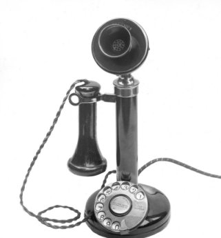
| With Solid Back Transmitter and exchange number label around the mouthpiece | With Solid Back Transmitter housing but without the number label around the mouthpiece | |||||||||||||||||||||||||||||||||||
|
Automatic Pedestal Telephone Standard pedestal instrument for GPO CB or Automatic exchange circuits. Used with a Bellset, No. 1. In 1924 the Telephone No. 150L was introduced, which superseded the Telephone No. 124. Similar to earlier telephones in that it was a candlestick model, it was innovatory in introducing the dial to most subscribers for the first time. Reflecting the progress of automatic switching, the dial operated the automatic exchange switching mechanism by sending out a series of electrical impulses corresponding to the number being dialed. It was no longer necessary for the operator to connect all calls and provision was made for a dial. Where a Telephone No. 150 was still connected to a manual exchange, the aperture in the base of the telephone for the dial was covered by a dummy insert (used as a number label holder) which could be replaced by a dial when the exchange was converted to automatic working. When this telephone was introduced it used the Transmitter No. 1, to which was affixed the exchange number, and the dial blank plate was a Dial, Automatic, Dummy No. 2. Around 1932 the Transmitter No. 22 replaced the Transmitter No. 1 and as there was no provision on the transmitter for the exchange number the Dial, Automatic, Dummy No. 4 was introduced, for C.B. telephones, which had a recess for a dial label. The picture above shows the two styles of transmitter head which could be found on a Telephone No. 150. To the left is the later style Bakelite 'Transmitter No. 22' which accepted the 'Transmitter Inset No. 10' which was superseded by the 'Transmitter Inset No. 13'. The transmitter head to the right is the older style solid back 'Transmitter No. 1'. The early type with the Transmitter No. 1 could have a Label No. 43 fitted between the speaking tube and the transmitter body. This label advised of the Exchange name and number. All models were fitted with Dial No. 10 and used with a Bellset No. 1 or 25. Some of the early Dial No. 10's had a smaller dial label holder. The correct Bellset must also be fitted to ensure good transmission quality. All models have no internal components except for switch hooks and the phone requires the correct Bellset to work properly (see above). The switch hook springs in this telephone were totally insulated with no connection to the casing, which made the phone electrically safe. The switch hook consists of three contacts that all make together. Many Telephones No. 150 were converted from Telephones No. 2 by the GPO. These can be identified by the number 2 being crossed out and a number 150 stamped nearby on the top of the microphone swivel posts (see pictures below). Early table telephones were connected to the internal wiring with a Strip, Flexible Cord Connection. Click here for more information. See also the Telephone Efficiency Committees Report on Common Battery Area telephones.
Telephone includes (1928):-
Telephone includes (1946 and 1956):- Circuit diagram - N250. Circuit diagrams - AT 1729 & CB 1403. Paster Diagram - Click here. Drawing - No. 9179. Terminal Markings
Click here for pictures of a Candlestick before refurbishment Click here for Candlestick construction and how to dismantle the phone Candlestick Manufacturing (Messrs Keitmann) How to convert to Plug and Socket Collectors Information - what to look for Telephone mouthpiece sanitisers
This is an early Telephone No. 150CB.
Post 1932 Telephone No. 150CB.
This pillar-type telephone for central battery operation is the one familiar to nearly all collectors as the classic ‘candlestick’ telephone. In Australia they are designated Types 38AT (automatic), 38MT (magneto) and 38CBT (central battery). Reproductions of this telephone, made in some cases from the original tooling, are common and in Australia all piece parts are available separately. Collectors may consequently encounter many convincing examples that are in fact made entirely or partly from reproduction parts. Introduced in 1924, it was the PO’s first standard design of dial table telephone. When the telephone was to be used on manual exchanges the space for the dial in the base of the telephone was covered by a dummy insert (used as a number label holder) that could be replaced by a dial when the exchange was converted to automatic operation. Manufactured by: Ericsson, STC and others. Colours: Black was the standard colour although subscribers could theoretically pay to have these telephones painted another colour (so long as they also paid to have them restored to black afterwards). Variants: In the early 1930's the solid-back microphones originally fitted were mostly replaced with a Bakelite moulding containing a standard carbon microphone inset (these assemblies were made by Siemens Brothers). They were replaced because the later Transmitter was much more resilient to noise and transmission faintness. In Australia these refurbished telephones were known as Type 138. In consequence a telephone with its original solid back transmitter is relatively rare item. This applies both in Britain and in New Zealand. Ron Kay notes that some collectors there assume that their Western Electric style candlestick is a Siemens phone because the new replacement microphones have the name Siemens Brothers moulded on the Bakelite mouthpiece. Similar modifications were also made in the USA, where the Bakelite replacements are known as ‘Bulldog transmitters’; some British collectors incorrectly use the name for the Siemens transmitters as well. Question and answers on Candlesticks Question: Should the Bakelite
earpiece cap have a notch moulded on to the face and why is it
there on some and not others? Question: Why do some of the switch
hook arms have solid plates and others hole cut in and what does
the F stamp stand for? Question: Can anyone tell me what the original
paint finish is on the stem and base of a Telephone No. 150? Question: Do
you need to split the stem and the base? Question: How
do you remove the Bakelite grommet on the base in one piece? Question: Should
the Bakelite earpiece cap have a notch moulded on to the face and
why is it there on some and not others? Question: Is
it possible to get replacement rubber rings for the base? Question: What is the Bell Receiver coated with? Question: Do I need a separate Bellset for this phone to work? Question: Did the GPO Candlestick phones come with any transfers or
polished brassware? |
||||||||||||||||||||||||||||||||||||
Last revised: January 18, 2026FM | ||||||||||||||||||||||||||||||||||||


