P.O. ENGINEERING DEPT.
ENGINEERING INSTRUCTIONS
TELEPHONES
STATIONS
A3919
Issue 2, 8.9.47
TELEPHONE
No. 254
PORTABLE TELEPHONE FOR 4-WIRE AND 2-WIRE WORKING
1. General
 Telephone
No.254 was introduced for use by engineering
staff in the provision of private wires for the Services and for cases of
emergency; it will now be retained for use by the engineering staff in providing
temporary speaker facilities in special cases, e.g. 'setting-up' operations on
new cable routes where the normal speaker facilities are not available. Telephone
No.254 was introduced for use by engineering
staff in the provision of private wires for the Services and for cases of
emergency; it will now be retained for use by the engineering staff in providing
temporary speaker facilities in special cases, e.g. 'setting-up' operations on
new cable routes where the normal speaker facilities are not available.
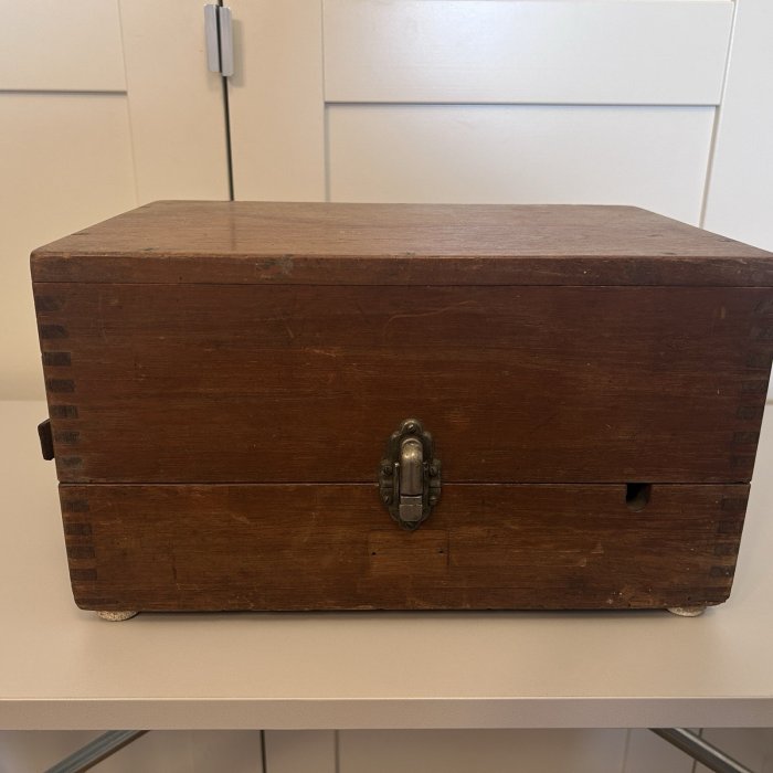
2. Description
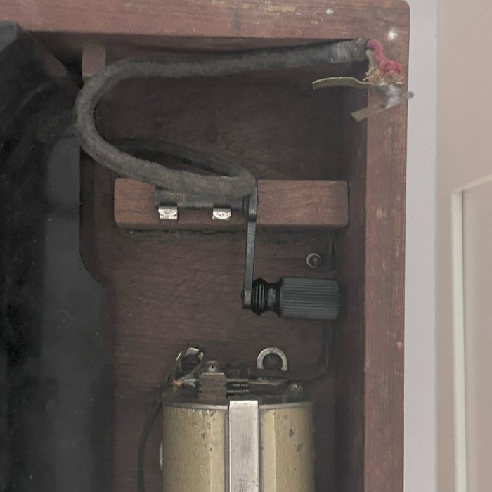
The telephone
consists of a standard "Telephone No. 394LB", together with a generator
and subsidiary items, mounted in a wooden case 13in. x 7in. x 9in. The case
is provided with a carrying handle and is fitted with sliding-back flap hinges,
so that the lid may be removed, if required. It is necessary to open the lid
fully to give access for operating the telephone.
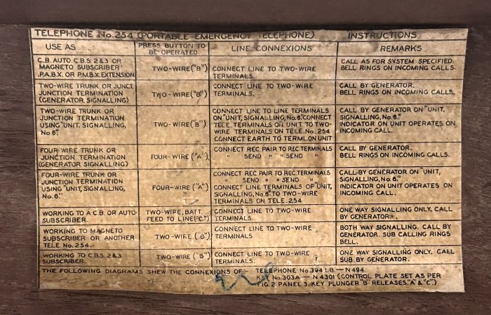
3. Facilities
The Telephone No. 254 provides the following
facilities:-
(a) 4-wire working. For
terminating 4-wire private-wires with generator-signalling over the phantom or
(using the telephone in conjunction with "Unit, Signalling, No. 6")
for terminating 4-wire private wires with D. C. signalling.
(b) 2-wire
working. For use on
2-wire circuits as follows:-
-
On subscribers circuits connected
to C.B., Automatic, C.B.S. Nos. 2 and
3, & Magneto exchanges, and also on P.M.B.X.'s and P.A.B.X.'s.
-
On
private-wires with generator signalling.
-
On
private-wires with D.C. signalling, using the telephone in conjunction with
a 'Unit, Signalling, No.6'.
-
On
trunk and junction terminations with generator signalling.
Stock provision of Telephone No. 254 has not been arranged to cater for
exchange areas requiring dials of S, B, or W type. If a "Dial, Automatic, S. S.
No. 10 LA" is not suitable, a "Dial, Automatic, S. S. No. 10" for the area concerned should be requisitioned and fitted locally.
(c) 2-wire working, with
battery, feed to line. For feeding transmitter current to line for C. B. or
Automatic subscribers' instruments.
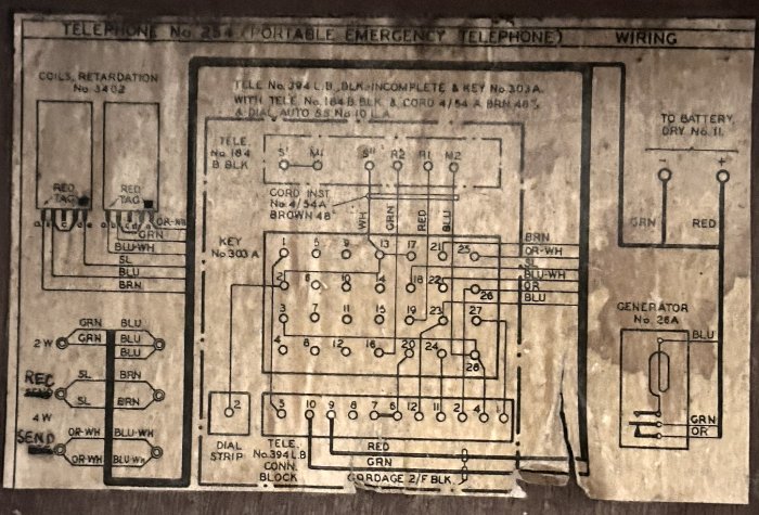
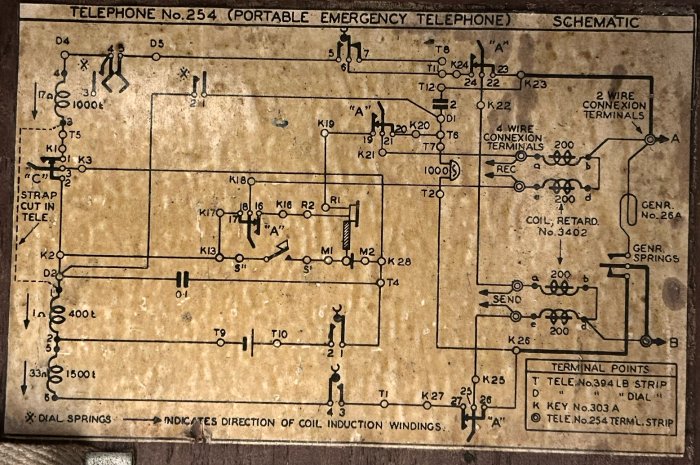
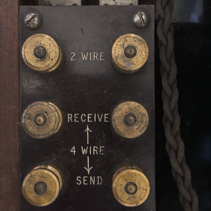
4. Circuit
-
The connexions are shown
on Diagram N354; a copy of each of
the three panels is fixed inside the lid.
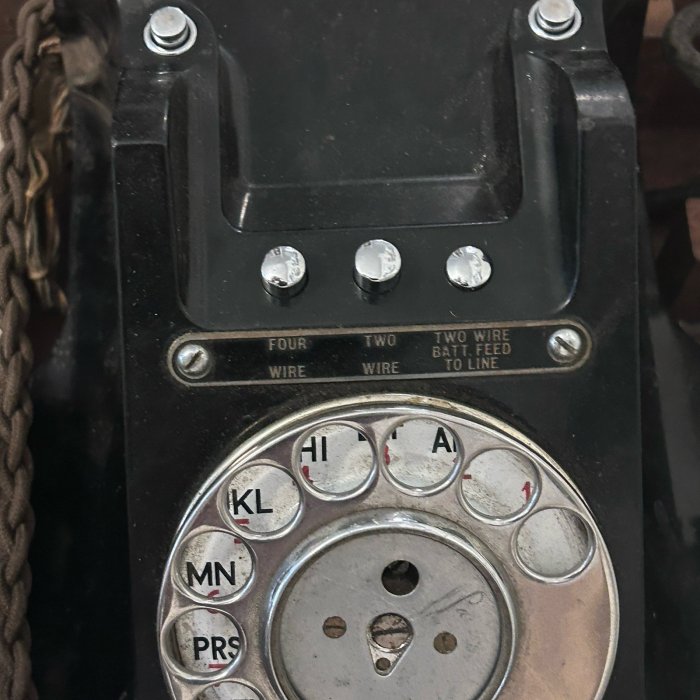
-
A "Key
No.303A" (with three plungers), arranged as per Fig. 2, Panel 3, Diagram N
4301, provides switching according to requirements.
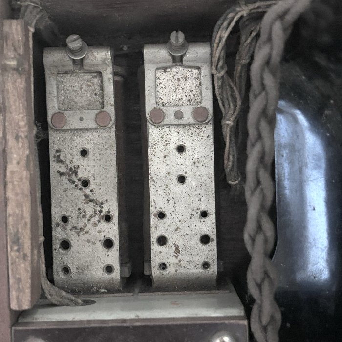
-
"Coils,
Retardation, No. 3402" are arranged to give access to the phantom of the
4-wire circuit for signalling purposes.
5. Method of connecting the
Telephone
Diagram N354 shows the method of connecting the telephone for all
of the conditions referred to in par.3.
6. Requisitions
Including maintenance-exchange requisitions, should circulate
through the normal channels.

|