General Information on 700 Type Telephones.
700 Type telephone circuit
description.
700 Regulator operation.
Many models made by British Ericsson - model N1340
.
How to wire your Telephone 706 to make it work on Plug and Socket.
How to wire your Telephone No. 710 to make it work on Plug and Socket
.
Some model were made by British Ericsson - their model N1342A
.
How to remove the case.
Dismantling a Handset No. 3.
Restoring the plastic cover and handset.
General fault finding on your phone.
Bell gong
change.Circuit diagram - N810.
Diagram for the Additional Buttons - N849.
Diagram for the Auxiliary Switches - N848.
Drawings - 91606, 91607/0,
91607/1, 91607/2 &
93011.
Specification - S753.
Introduced circa 1964.

TELECOMMUNICATIONS INSTRUCTION
C MARKETING
INSTALLATION
3 Internal
B1003
ISSUE 2, APRIL 1977 TELEPHONE
No. 710
Distribution and Facilities
SCOPE OF INSTRUCTION
This Instruction describes the Telephone
No. 710 and the various additional items that can be fitted to cover its range of facilities. Installation instructions are given in B1000.
Many of the parts and adapters used on the Telephone
No. 710 are identical with those of the Telephone No. 706, which is described in B1001. Only those items peculiar to the Telephone
No. 710 are described in this Instruction.

GENERAL
The Telephone No. 710, developed from the conventionally wired
Telephone No. 706, can be adapted for many uses beyond the scope of the latter by fitting extra apparatus. The Telephone
No. 710 is for use at installations where any of the following facilities are required:-
(a) One to four press-buttons, with or without gravity-switch release.
(b) Press-buttons which are required to operate from one to four change-over spring-sets.
(c) Auxiliary gravity-switch springs up to a maximum of 2 c/o or 1 c/o
plus 2M.
(d) One or two internal lamps.
(e) Combinations of the above.
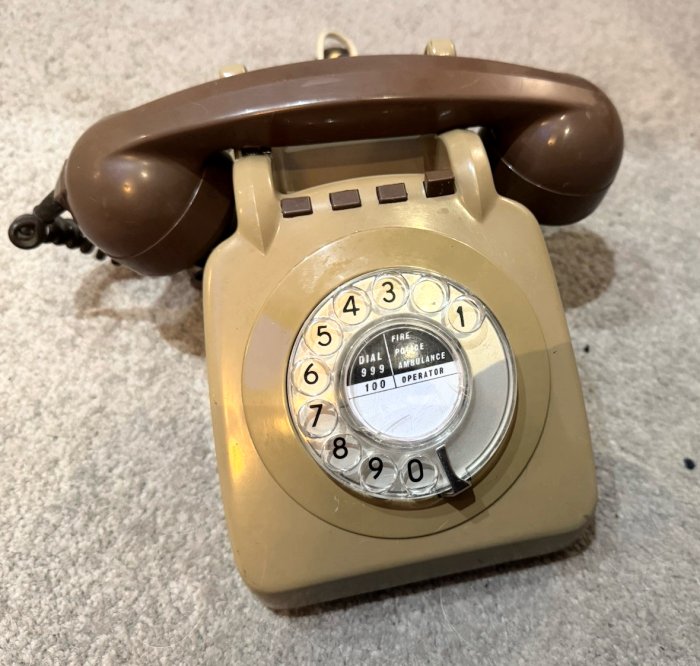
The Telephone
No. 710F (Colour) is available in Black, Grey and Ivory
(Ivory is shown in the picture above). It is supplied without line cord and terminal block since different types of these items are required to meet the various requirements of the telephone. The appropriate cord and terminal block should be requisitioned separately according to the use of the telephone.
COVER
The Telephone
No. 710 is supplied with a cover, Part 5/DCO/627 (Colour), which is similar to that fitted on the Telephone
No. 706 but has positions for four press-buttons between the front cradle-rest ribs. The four button holes are normally fitted with clip-in dummy buttons, Parts 2/DBU/261 (Colour). Four button retaining pins, Parts 1/DPI/203, are pressed into slots in the inside of the cover for use when buttons are to be fitted. The two fixing lugs on the inner front edge of the Telephone
No. 706 cover are omitted from the Telephone No. 710 cover to facilitate fitting when buttons are included.
GRAVITY-SWITCH AND LATCH MECHANISM
This mechanism is mounted on two vertical brackets riveted to the telephone base. The gravity-switch plunger arms are long to ensure that the gravity-switches and press-button latch plate are fully operated by the weight of the handset.
The gravity-switch spring-set consists of a bank of palladium contact, 1000 type key springs which are comb-operated and enclosed in a plastic dust cover.
The spring-set is mounted on a bracket which has an extension to form a mounting for a lamp fitting, when required. The spring-set bracket is secured to two studs fitted to the left-hand vertical gravity-switch bracket by two nuts, Parts 1/DNU/87. The fixing holes in the mounting bracket are elongated to allow the depth of engagement of the spring-set with the gravity-switch lever to be adjusted. A similar spring-set bracket, without spring-set, is provided on the right-hand vertical gravity-switch bracket to provide a mounting for a second lamp-fitting.
Two plastic dust covers are sprung into holes in the vertical gravity-switch brackets to protect the press-button spring-sets, when fitted. The rear dust cover, Part 1/DPL/2055, is static and the top dust cover, Part 1/DPL/2056, is hinged to facilitate fitting of the spring-sets. The dust covers are omitted in latest supplies.
The press-button latch plate is fitted in bearing holes in the two vertical gravity-switch brackets and is retained in position by the two gravity-switch spring-set brackets. Six latches, Parts 1/DLA/62, are fitted to the latch plate, four to control the looking of the press-button plungers and two to provide gravity-switch release of these plungers. The positioning of the latches to provide the various facilities is shown in Diagram N848. The latch plate is restored by a leaf spring attached to the latch plate and tensioned against part of the gravity-switch bracket.
The press-button plungers, Parts 2/DPL/380, are made of a self-lubricating plastic material, early supplies were metal. The stem of each plunger is fitted with a spiral restoring spring, Part 1/DSP/1500 and fits into a square hole in the front plate of the gravity-switch bracket. A ratchet tooth shaped step on the plunger passes into a slot in the front gravity-switch bracket to engage with the latch to provide the locking facility and to limit the upward travel of the plunger. The top face of the front gravity-switch bracket has four markings, A, B, C and D which are referred to on Diagram N848, to identify the four press-button positions
(see picture below).

DIAL FIXING
The dial mounting is identical with that used in the Telephone
No. 706 but the two fixing brackets are different. The top support is a small bracket secured to the front gravity-switch bracket and the lower support consists of a plate located across the top of the bell gongs which has an extension turned down centrally in front of the gongs.
AUXILIARY UNITS
Diagram
N4700 gives a complete list of the auxiliary units used on the Telephone
No. 710, Diagram N848 gives the wiring of the various adapters and Diagram
N849 shows the various press-buttons that are available.
Auxiliary Gravity-Switch Spring-Sets
These spring-sets are similar to the gravity-switch spring-set provided with the telephone but the mounting bracket is formed to permit mounting of the right-hand vertical gravity-switch bracket. When mounted the auxiliary gravity-switch spring-set replaces the existing gravity-switch bracket without spring-set that is fitted to the right hand vertical gravity-switch bracket.
See picture below.

Adapter, Local Battery No 4
This adapter consists of an auxiliary gravity-switch spring-set, having one make contact unit, and an inductor mounted on a bracket. The mounting bracket is similar to that used with auxiliary gravity-switch spring-set and is secured to the telephone in the same position by the same method.
Press-button Spring-sets
These spring-sets are of similar construction to the gravity-switch spring-sets, with the exception of the Switch
No. 5A-4 which is a microswitch. Each spring-set is mounted on a bracket which has a pointed projection on the lower end and a stud fitted with a captive nut on the upper end.
 |
 |
| Early Switch No. 5A-4 identifiable by the
fixing screw on a metal bracket |
Later Switch No. 5A-4 identifiable by a
lug instead of the fixing screw |
To fit these spring-sets, fully loosen the captive nut and slide the spring- set into position beside the press-button plunger. When correctly positioned the projection on the mounting bracket fits into a square hole in the lower part of the front gravity-switch bracket and the stud fits into a slot beside the top of the press-button plunger. Secure the spring-set in position by tightening the captive nut.
Press-Buttons
The range of press-buttons available is shown on Diagram
N849. Parts 1 and 3/DBU/262 are fitted with a slide that engages with the button retaining pin to provide a locking action independent of the latch and gravity-switch mechanisms.
To fit a press-button to the telephone case, push out the existing dummy button and retaining pin, Part 1/DPI/203, insert the press button into the case with the engraving facing to the front, pass the retaining pin through the elongated hole in the press-button and press the retaining pin into the two slots in the inside of the case. When fitting Parts 3/DBU/262 use a Part 1/DPI/ 205 in place of the existing retaining pin, Part 1/DPI/203. Parts 1/DPI/205 are made from phosphor bronze strip and the ends are formed into two wings which engage with the sides of the two slots in the case to provide a more secure fixing
(see button to the right in the picture below). A Part 1/DPI/205 may also be used with Parts 21-37/DBU/260 if the Part 1/DPI/203 provided with the telephone is found to be a loose fit in the case.
A press-button, without spring-set, may be fitted for the purpose of releasing another press-button from its locked condition. It is necessary for the plunger of the press-button providing this facility to be supported by a Part 1/DST/26. The Part 1/DST/26 is similar to the spring-set mounting bracket and is mounted by the same method.

Lamp fittings
One or two Lamp Fittings No. 16A may be fitted to the mountings provided on the gravity-switch spring-set brackets.
To fit the lamp fittings remove the slotted nut, plain washer, tag and insulating bush from the lower end of the lamp fitting. Offer the lower end of the lamp fitting to the top face of the mounting bracket and insert the insulating bush into the mounting bracket from below. Replace and secure the tag, plain washer and slotted nut in that order.
When these lamp fittings are used, replace the existing cover, Part 5/DCO/627 by a Part 6/DCO/627 which has a clear lens fitted to each side of the front sloping face. A Lamp No. 26, requisitioned separately, is used with the Lamp Fitting No. 16A.
When a lamp fitting is fitted to an Adapter, Local Battery No. 4 it may be necessary to omit the plain washer from the lamp fitting to prevent the fixing nut fouling the inductor.
REPLACEMENT PARTS
The following is a list of replacement parts, additional to those parts common to the Telephone
No. 706, which are available:-
| Description | Vocab name | | Pin, retaining | Part l/DPI/203 | | Button, dummy | Part 2/DBU/261 (Colour) | | Cover | Part 5/DCO/627 (Colour) | | Latch | Part 1/DLA/62 | | Plunger | Part 2/DPL/380 | | Spring, plunger | Part 1/DSP/1500 | | Nut, hexagonal | Part 1/DNU/87 |
The Telephone
No. 710 is superseded by the Telephone No. 740. However, there are certain facilities of the
Telephone No. 710 which cannot be achieved using the
Telephone No. 740. These are described in Diagram
N848 and include Local Battery operation, and certain types of independently locking press-buttons. Telephone No. 710CB was supplied by
ETL, their Model N1342.
Telephone No. 710L was supplied by
ETL, their Model N1902.
How to remove the case from a Telephone No. 706 or 710
- Remove handset and slacken the two screws underneath the handset.
- Lift the rear of the case upwards and forwards.
- Once clear of the dial, pull the case away from the front of the base
plate to remove completely.
Re-fitting is the process in reverse, except you may have to move the casing
dial ring to locate it over the dial.
Additional Information
| Model | Mark |
Black |
Grey |
Ivory |
Introduced |
Remarks |
| Tele No. 710 | Mk 1 |
y | y |
y |
3/60 | |
| Tele No. 710CB | Mk 1 |
y | y |
y | 3/60 |
Dial Auto Dummy No. 6 fitted | | | Mk 1 |
y | y |
y | Refurbished |
| | | Mk 1 |
y | y |
y | 11/63 |
Dial
Auto Dummy No. 7 fitted | | Tele No. 710F | Mk 1 |
y | y |
y |
11/69 | Fitted with a dial | | | Mk 1 |
y | y |
y | Refurbished |
Fitted with a dial | | Tele No. 710L | Mk 1 |
y | y |
y | 10/59 |
Fitted with a dial |
| | Mk 1 |
y | y |
y | 9/63 |
710/0 for Diakon parts |
| | Mk 1 |
y | y |
y | 9/63 |
710/1 for ABS parts |
 |