|
Telephone
No's 9531 & 9631
 The
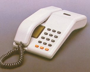
Viscount Super 4 Telephone is available in two versions. The Telephone No. 9531R (shown
to the right) contains a 10pps
Loop Disconnect keypad and the Telephone No. 9631AR is for use on MF4 signalling
systems. The
Viscount Super 4 Telephone is available in two versions. The Telephone No. 9531R (shown
to the right) contains a 10pps
Loop Disconnect keypad and the Telephone No. 9631AR is for use on MF4 signalling
systems.
Key Facilities:-
-
On-Hook Monitor Amplifier, pressing the button at the top of the instrument will
connect the amplifier to line. The button maybe locked down by sliding it to the left,
this will automatically release if the handset is lifted.
The monitor amplifier output may be regulated by using the tone caller volume control.
-
4 Number memory, each number is stored (with the line connected and the handset
lifted) by holding down the 'MS' button, pressing the keypad button (1-4) it is to be
stored under and then keying in the number to be stored.
Stored numbers are transmitted by pressing the 'MR' button followed by the keypad button
that the number is stored under.
-
Last (Stored) Number Redial, an enhanced version of last number redial enabling users
to store the number they have just dialled. The number may be stored by pressing the
'MS'
button at any time after the number has finished pulsing out and before replacing the
handset at the end of the call.
The Stored Redial number may subsequently be transmitted by pressing the 'MR' and then the
'MS' button.
-
Notepad Memory, by pressing the '#' button once, users may then use the keypad to
enter a number into the 'Notepad' store whilst a call is in progress without sending
pulses to line.
The Notepad Memory number may subsequently be transmitted by pressing 'MR' and then the
'N' button.
-
Battery back-up, users may fit batteries in the base compartment of the telephone to
retain memory if the telephone is taken off-line.
-
Secrecy, transmission and reception are both cut off by holding down the 'N' button to
provide secrecy.
-
PBX Recall, Viscount 4 Telephones are provided with earth-loop recall facilities. MF
versions (Telephone No. 9631AR) may be converted to provide Timed-Break recall facilities if
required by shifting the connector fitted to the recall switch lead from plug to plug 1
(on upper circuit board). The Notepad and Redial stores can both store numbers of up to 20
digits, a tone will be heard in the receiver inset if attempts are made to enter longer
numbers. There is no facility for storing PBX access pauses in any of the stores in the
Viscount 4. PABX users should therefore manually key any exchange line access digits
before attempting to send any stored numbers. This also applies to the Last (stored)
Number Redial facility which will automatically delete manually keyed access digits from
it's store, preventing them from being sent out twice.
Incoming calls are signalled by a tone ringer with adjustable volume control situated on
the underside of the telephone.
Colours: Navy Blue and Ice Grey
Telephone No. 9641AR
Known as the Viscount Super 12, this phone is similar to the Super 4 above
except that it has 12 memories.
Key features:
- Pulse and tone dialling
- Earth and time break recall
- 12 Indirect memories
Colours: Navy Blue and Ice Grey
Additional Information
Viscount Super 4
Made by STC Telecommunications Ltd
APPROVAL STATUS
This instrument is approved as supplied, for connection to the BT telephone system under
approval numbers:-
Viscount No. 9531R - S/10000/3/E/500045
Viscount No. 9631AR - S/10000/3/E/500046
Viscount Super 4 telephones have a REN of 1.
To convert from Earth-loop recall to Timed break, shift recall switch lead from
PL5 to PL1
(on upper PCB).
PARTS
| DESCRIPTION
|
BT ITEM CODE
|
| Telephone No. 9531R Ice Grey |
870020 |
| Telephone No. 9531R Beige |
87002l |
| Telephone No. 9641AR Navy Blue |
870036 |
| Telephone No. 9641AR Ice Grey |
870037 |
| Bracket, Telephone No. 26A Grey |
436451 |
| Bracket, Telephone No. 26A Beige |
436452 |
| Cord, Connection No. 4/506, 3000mm Charcoal |
512300 |
| Cord, Connection No. 4/506, 3000mm Cream |
512301 |
| Battery LR03 (2 required) |
171418 |
The stored number memory facility of the Viscount 4 draws approximately 22ma line
current at 50 Volts whilst the instrument is on-hook and may result in low resistance loop
line-test conditions.
When off hook the electronic keypad and transmission circuitry may give high resistance
telephone loop conditions as with other self contained press-button telephones.
Viscount 4 telephones are line powered and require no external power supplies. The Monitor
Amplifier is powered by telephone loop current which should not be less than 15ma for
correct operation.
Line current is drawn whilst the instrument is on-hook to maintain stored number memory.
The telephone should be left connected to line in normal use otherwise stored numbers will
he lost after approximately 5 minutes Off Line.
Batteries are not required for the normal operation of the Viscount 4 but may be fitted to
retain stored numbers if the telephone is likely to be disconnected from line or if other
telephones are used on the same line. Battery provision and replacement is the customers
responsibility, AAA sized Leakproof Alkaline cells (2 off) are recommended.
Battery drain is typically 15ma off-line and 7ma on-line giving several years battery
life.
Viscount Super 4 telephones have fairly good immunity against Radio Frequency interference
(RFI) from 100kHz to 10MHz but poor immunity at higher frequencies.
Converting the recall type
Telephone
No. 9631AR
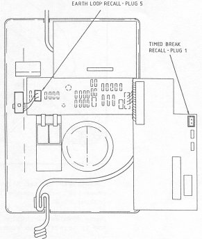 Conversion to Time Break Recall Conversion to Time Break Recall
-
With a cross head screwdriver remove the fixing screw on the top of the
phone.
-
Pull the base from the top casing, whilst holding down the hook switch.
-
Lifting from the back of the case will ease separation.
-
The keypad circuit board must be turned over to expose the Plug 1. Watch
out for the ribbon cable that links the two circuit boards.
-
Remove the plug from the socket Plug 5 and move to socket Plug 1 on the
keypad board.
-
Before re-assembly ensure that the two circuit boards are correctly
seated.
-
When re-assembling the phone locate the lugs nearest the key pad first.
Telephone
No. 9641AR
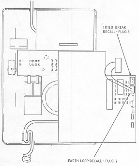 Conversion to Time Break Recall Conversion to Time Break Recall
-
With a cross head screwdriver remove the fixing screw on the top of the
phone.
-
Pull the base from the top casing, whilst holding down the hook switch.
-
Lifting from the back of the case will ease separation.
-
To turn the internal smaller board over a four way fly lead must firstly
be detached.
-
Remove the plug from the socket PL2 and move to socket PL1 as shown in the
diagram to the right.
-
Before re-assembly ensure that the fly lead and the two circuit boards are
correctly seated.
-
When re-assembling the phone locate the lugs nearest the key pad first.
|