|
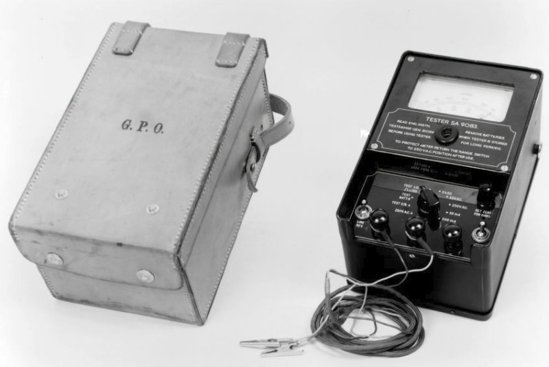
The Tester SA9083 was introduced as a universal line
circuit tester for linesmen. It differs from the standard tester in so
much as it has a line reversal key.
The early versions, the Mark 1 to Mark 3, were steel
cased and used a 67.5volt battery. The Mark 4 was size reduced and had
much smaller batteries, probably due to technology miniaturisation.
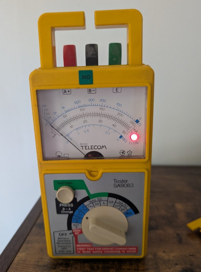
Using the Tester SA9083 (Mark 4 onwards)
 This instrument was designed specifically for testing telephone lines and equipment so some of its features are not needed for general purpose
testing. It has a 12 position switch which selects the various ranges. The first
position, although marked "off", is the AC voltage measuring position. Up to 250V AC can
be measured and the test probe should be connected to A+ and B- as for all other ranges
except the insulation test range 12. The reason why this position is marked
"off" is because in any other position of the switch the battery is in circuit and would be discharged unnecessarily, so always turn the switch fully
anti-clockwise.
This instrument was designed specifically for testing telephone lines and equipment so some of its features are not needed for general purpose
testing. It has a 12 position switch which selects the various ranges. The first
position, although marked "off", is the AC voltage measuring position. Up to 250V AC can
be measured and the test probe should be connected to A+ and B- as for all other ranges
except the insulation test range 12. The reason why this position is marked
"off" is because in any other position of the switch the battery is in circuit and would be discharged unnecessarily, so always turn the switch fully
anti-clockwise.
Positions 2 and 3 are special circuits for testing GPO equipment and batteries
and are not for other use.
Position 4 is the high ohms range, with the probes touched together the pointer should indicate zero ohms. When measuring resistance then multiply the scale, reading
by 100. A further use for this range is, for testing the goodness of capacitors. When the
probes are connected across a capacitor and the push button is engaged, the meter movement will
deflect on an amount depending upon the value of the capacitor. When the probes are first
applied, the pointer will move over and fall back to zero if the capacitor is
good. If it stays over, then there is a leak. If you care to, you could note the deflection with various capacitors which would give you
some idea of the value of an unknown capacitor.
Position 5 is again an ohms range - use as for previous position but don't
multiply the scale reading by 100. This should be regarded as the low ohms range.
Position 6, 7 and 8 are for reading DC voltage up to 250V.
Positions 9, 10 and 11 are for reading DC current, 5A on range 9, 500mA on range
10 and 50mA on range 11. A useful thing to remember when using these current ranges is that should you have connected your instrument the
wrong way round and you are getting a negative reading, then the push switch on the right-hand side reverses the connection
of the meter and will give you a positive reading.
Position 12 is the insulation testing range. To use this range you must move the
probes between B- and E. In this switch position the internal generator
increases the voltage from 9 to approximately 150 so you are testing insulation at quite a high voltage. You will get a reading on the
bottom scale up to 5M but a good insulation should show no reading, this is what is known as infinity.
Additional
Information
Technical Instruction - Mark 1 to Mark 3
Technical Instruction - Mark 4 onwards
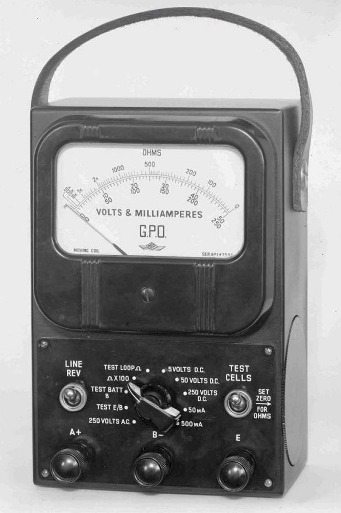
Tester SA9083 Mark 1
Steel cased faultsman's test set,
introduced circa 1949.
Identified by 7 position range switch
and set zero thumbwheel on the right hand edge of the case.
Superseded by the Tester SA9083 Mark 3
circa 1960.
Ranges:-
0-5, 0-50V, D.C.
0-250V, A.C.
0-50K, 0-5M Ohms
Test E/B.
Test Battery B.
To be requisitioned separately:-
1 x Battery, Dry No. 18.
1 x Cell, Dry D.S. 7A.
To be requisitioned separately as
required:-
1 x Case, Instrument No. 6A, with 1 Strap, Carrying, No. 5,
or 1 Strap, Carrying, No. 6.
Dimensions - 9" x 5.25" x 4.2".
Drawing - CD683/0.
Circuit diagram - SA9083/0.
Tester SA9083 Mark 2
Steel cased faultsman's test set,
introduced circa 1951.
Identified by 10 position range switch
and set zero thumbwheel on the right hand edge of the case.
Ranges:-
0-5, 0-50, 0-250V, D.C.
0-250V, A.C.
0-50, 0-500mA, D.C.
0-50K, 0-5M Ohms.
Test E/B.
Test Battery B.
To be requisitioned separately:-
1
x Battery, Dry, No. 18.
1 x Cell, Dry, R 20.
To be
requisitioned separately as required:-
1 Case, Instrument No. 6A,
with 1 Strap, Carrying, No. 5, or 1 Strap, Carrying, No. 6.
Drawing - CD683/1.
Circuit diagram - SA9083/1.
Dimensions - 9" x 5.25" x 4.2".
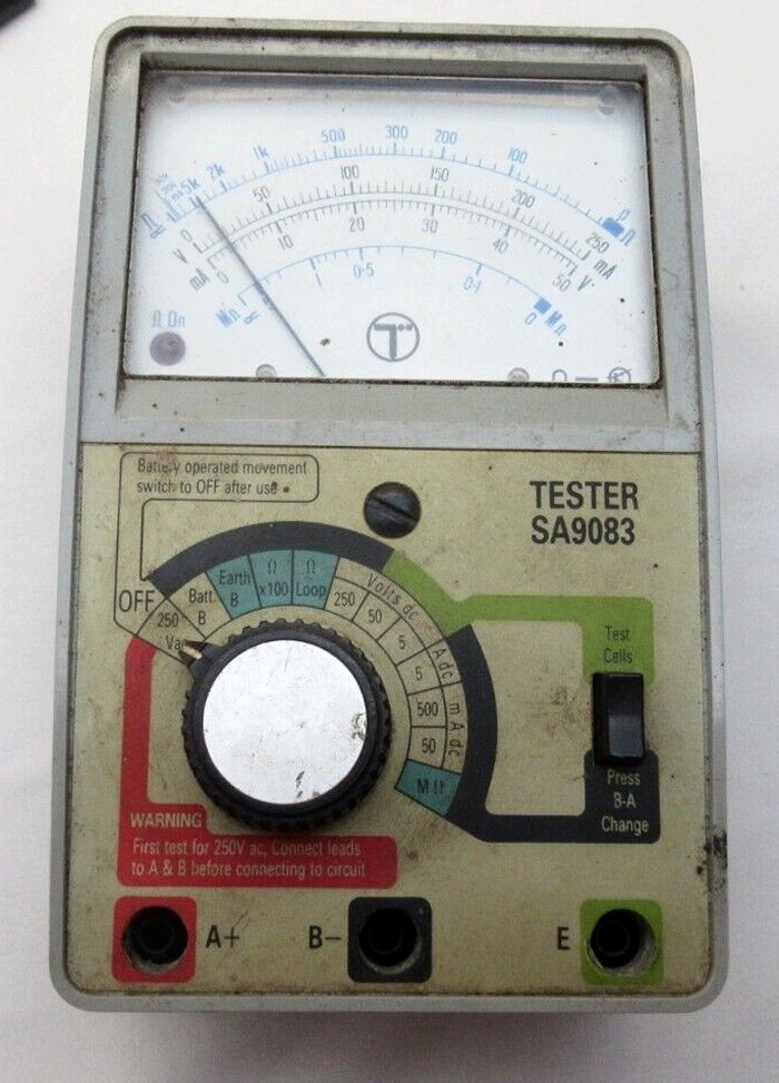
Tester SA9083 Mark 3
Steel cased faultsman's test set.
Identified by 10 position range switch
and set zero thumbwheel on the front panel. Both toggle switches are
now close to the cord terminals.
Ranges:-
0-5, 0-50, 0-250V, D.C.
0-250V, A.C.
0-50, 0-500mA, D.C.
0-50K, 0-5M Ohms.
Test E/B.
Test Battery B.
To be requisitioned separately:-
1
x Battery, Dry, No. 18.
1 x Cell, Dry, R 20.
To be
requisitioned separately as required:-
1 Case, Instrument No. 6A,
with 1 Strap, Carrying, No. 5, or 1 Strap, Carrying, No. 6.
Drawing - 90797 and 90990.
Circuit diagram - SA9083/2.
Dimensions - 9" x 5.25" x 4.2".
Tester SA9083 Mark 4
Plastic cased faultsman's test set,
introduced circa 1971.
Ranges:-
0-5, 0-50, 0-250V, D.C.
0-250V, A.C.
0-50mA, 0-500mA, D.C.
Loop, x100, M Ohms
Battery B
E/B test
Shunt
To be requisitioned separately:-
2
x Cell, Dry R6.
Drawing - CD2526 and 93157.
Circuit diagram - SA9083/3.
Dimensions - 6.55" x 3.75" x 2.45".
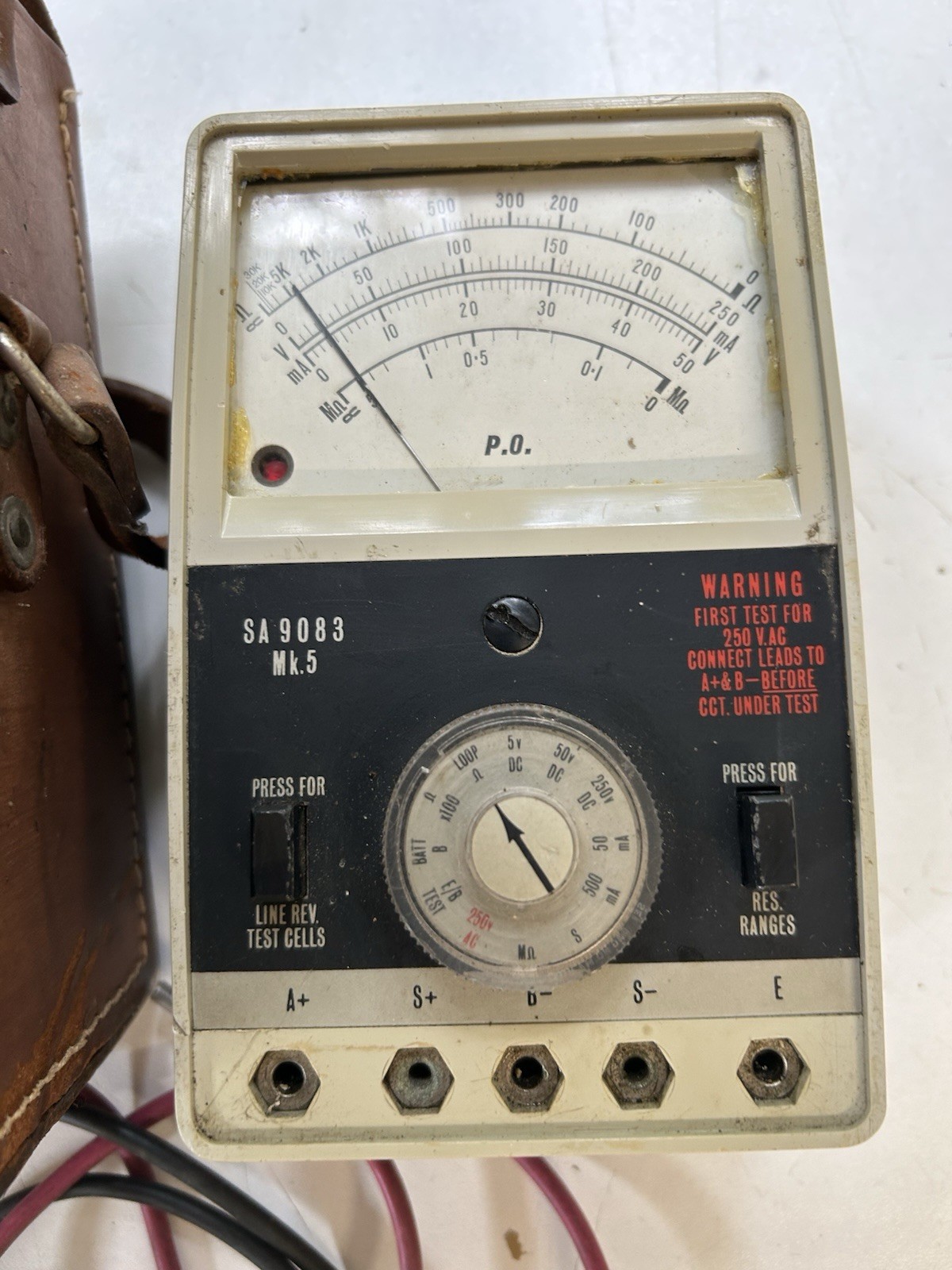
Tester SA9083 Mark 5
Introduced circa 1972.
Circuit diagram - SA9083/4.
Tester SA9083 Mark 6
Circuit diagram - SA9083/4.

Tester SA9083 Mark 8
Introduced circa 1977.
Circuit diagram - SA9083/5.

Tester SA9083 Mark 10
Comprises:-
1 x Tester, SA 9083.
1 x Case Instrument, No. 71 with Label No. 51013.
1
x Cord Test No. 1/60C.
1 x Cord Test No. 1/36H.
1 x Cord Test No. 1/36J.
2
x Clips Test No. 38A.
2 x Spikes Testing No. 10A.
To he requisitioned
separately as required:-
2 x Cells, Dry No. R6.
Tester SA9083 Mark 14

Tester SA9083 Mark 15
Tester SA9083 Mark 16
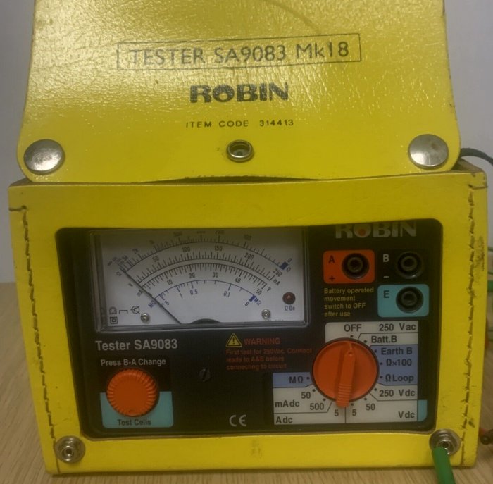
Tester SA9083 Mark 18
|