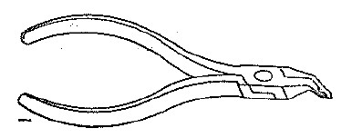
| Extractor No. 1
Pliers-shaped tool, 5.25in. long, with insulated
handles. The shape of the jaws is such that heat coils, lamp caps,
"clips, Test, No. 24" and "Links, M" can be firmly held and easily
removed from, or replaced, in position.
|

|
|
| Extractor No. 2
Pliers-shaped tool, 6in. long. Used for removing the
caps or covers fitted on Meters Nos. 1, 2, 3B, 8A, 8AN, 9A, 9C, 9D, 9F,
9G, 11A, 11B, 11D, 12A, 12B, 14A, 14B, 16A and 17A.
|
|
|
| Extractor No. 3
Pliers-shaped tool, approximately 5in. long, with
insulated handles. Used for removing or replacing the carbons fitted on
Protectors H.C. & F.
Also used with Carbons and Links No. 18.
|

|
|
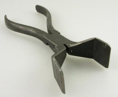
| Extractor No. 4
Pliers-shaped tool, approximately 5in. long, with
jaws tapering to a fine point; an adjustable screw is fitted in the
thick part of one of the jaws. The tool is used for removing the caps of
pilot lamps, the label holders which are fitted on switchboard jacks,
and Lamp Caps and Labels Nos. 1 and 2. The screw should be adjusted to
prevent the jaws from closing for a distance slightly smaller than the
width of the label holder or lamp cap being removed. This prevents the
label holder or lamp cap being damaged when a comparatively-heavy
pressure is applied to the handle, and also relieves the strain on the
thin tips of the pliers.
ATM Part No. L14341A.
ETL Part No. N8340.
|

|
|
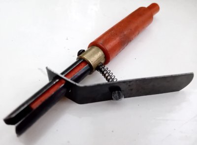
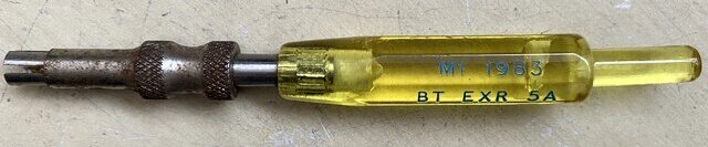
| Extractor No. 5 and 5A
Approximately 3in. long. A black Bakelite moulding
with a split tube made of spring steel fitted at one end, which is used
for removing Lamps No. 2. At the opposite end, the Bakelite is shaped so
that when the lamp has been replaced in position, it can be pushed right
home.
Earlier model is shown in top two pictures.
ATM Part No. L14581A.
ETL Part No. N8219.
|

|
|
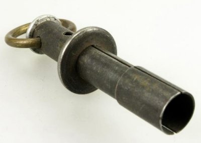
| Extractor No. 6
Consists of a split spring tube 2.5in. long, fitted with a
sliding washer. Used for removing Lamps No. 4.
|
|
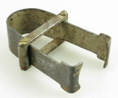
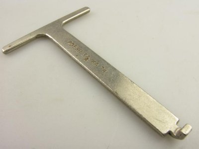
| Extractor No. 7
Consists of "U" shaped piece of flat spring steel, the ends of
which are turned inwards and shaped so that they will engage
with a groove provided in the covers of Indicators No. 600,
2700, 2800, 2900 and 3000. By means of this tool, the covers of
these Indicators may be removed. |
|
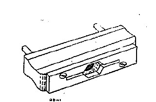
| Extractor No. 8
Consists of a hardwood block 2.25in. by 7/8in. by 0.5in., fitted
with a metal plate 2in. by 0.5in. and two prongs fitted at
l.6in. centres. In the steel plate, a slot and hexagonal hole is
cut. The tool is used for removing the covers fitted to W.E. Co.
relays. These relays are fitted with cylindrical covers, on some
of which two semi-circular rebates are made on opposite sides of
the periphery. The two prongs on the tool fit into these two
rebates and by a rotary movement in an anti-clockwise direction
the cover can be removed. The hexagonal hole fits a nut which is
fitted at the end of some of the covers, whilst the slot fits a
steel strip which projects at right angles from the end of other
types of cover.
|
 |
| Extractor No. 9
Pliers-shaped tool, 5.5in. long. The jaws are shaped to open the
locking rings fitted on Teleprinters No. 3A, 7A and 7B prior to
their removal.
|
 |
| Extractor No. 10 7 in.
long. Fitted with wood handle. The working end of the tool is
fitted with two hooks which are fixed 11 in. from each other.
Used for removing the anchor-pin springs of the transmitter
units fitted on Teleprinters No. 3A.
|
 |
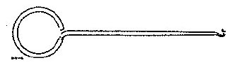
| Extractor No. 11 Consists of an
ordinary button-hook, 4.5in. long. Is used for the removal and
replacement of spiral springs fitted on Teleprinters 3A, 7A and
7B
|
 |
| Extractor No. 12
Pliers-shaped tool, 5.25in. long. The shape of the jaws allows
for the ebonite buffers fitted on A.E. Co., S.T. & Co. and
Ericssons' horizontal type relays to be securely held when being
removed or replaced. |
 |
| Extractor No. 13 Used in the removal
of 8mm ball-bearings from armature shafts of Telegraph machines.
Superseded by the Extractor No. 28.
|
|
| Extractor No. 23 Used on 2000 type selector racks
for the replacement of broken bank insulators.
|
 |
| Extractor No. 26 Used on the Relay, Polarized, No.
2B.
|
|
| Extractor No. 28 Used in the removal
of 8mm ball-bearings from armature shafts of Telegraph machines.
Supersedes Extractor No. 13.
|
|
| Extractor No. 29 For removing dial centre window of
Dials with clear finger plates i.e. Dial No. 21 clear.
Effectively a rubber sucker.
|
 |
| Extractor No. 30 For Removing Fuses
No. 64 from
Fuse-mounting No. 8064.
|
|
| Extractor No. 37A For extracting electronic
sliding card units.
|
|
| Extractor No. 40 For extracting Lamps, No.41A-F.
|

|
| Extractor No. 50 Used to remove Strips Connection
No. 237...from their holders.
|
|
| |
|