UNITS, AUTOMATIC, No. 4 | |||||||
|
Unlike other Units, Automatic used by the GPO (which were for used for public switching purposes), the Unit, Automatic No. 4 was a P.A.B.X and used on customers premises. The equipment was designed and produced for the GPO by the Standard Cables and Telephone Company (STC) and is similar in most respects to their 4002 type of P.A.B.X. All the GPO drawings and pictures are dated 1928. The system is based on the principles of the Western Electric Co's rotary system. This system was officially approved. Taken from a paper read at the IPOEE in
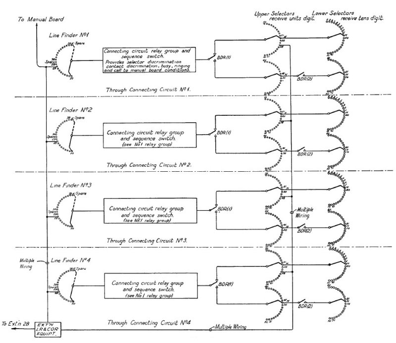
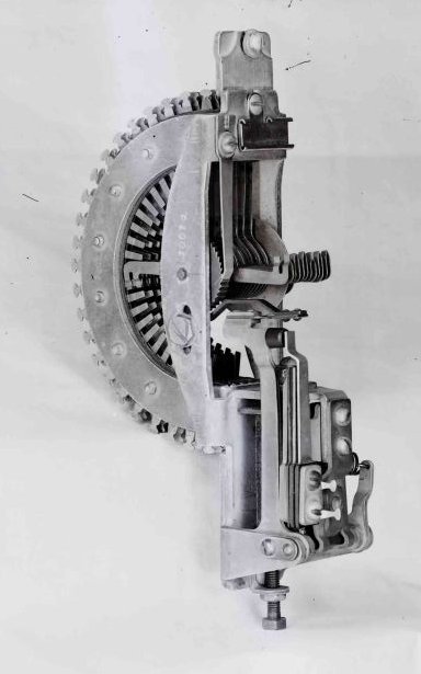
January 1932 The Unit Auto. No. 4 (S.T. & C. 4002 type P.A.B.X.) This installation is probably well known as it has now been a Post Office stock item for some years and quite a number are in service.The system operates on a line finder basis. The line finder uniselector is of the rotary line switch type with 22 point banks. Each selective mechanism contains two uniselectors both similar in construction to the line finder. These act as group selectors and are termed "upper" and "lower" selectors according to their position on the mounting frame.There is also a group of relays and a sequence switch in each connecting circuit which control the selective operations of the upper and lower selectors and the connections of the various tones, etc. A sequence switch is shown below. It contains eight cams lettered A to H which are mounted on a common spindle and electromechanically rotated. These switches perform functions equivalent to relay operations and reduce the number of relays required to a minimum, and the indicator associated with the spindle is useful from a maintenance point of view as it indicates the various stages through which the call passes.
Sequence Switch Mechanism - Parts
Sequence Switch Mechanism - Picture Automatic unit
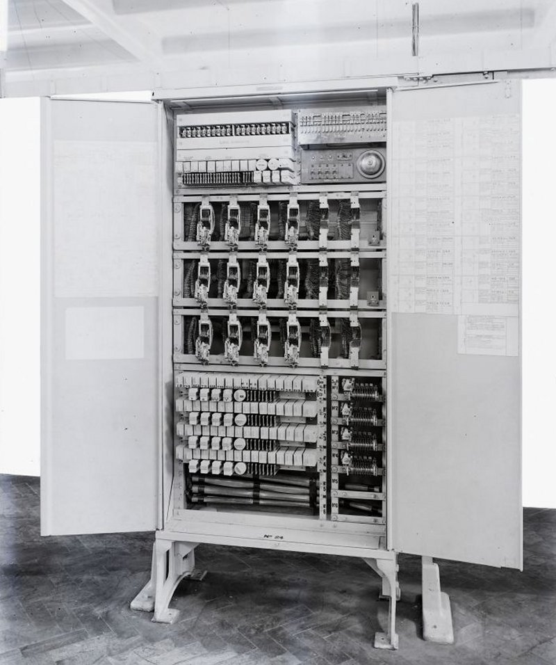
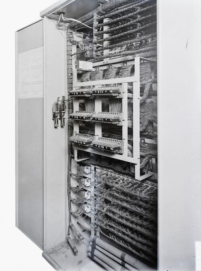
Front view
Rear view Automatic equipment There is provision for six connecting circuits with four connecting circuits or selective mechanisms initially equipped. Two more may be added when required, the necessary wiring and uniselector banks and sequence switch mounting plates being already in position. Other equipment. In addition to the automatic unit a manual board and ringing machine panel are required. The manual board is usually supplied from Post Office stock, a 10 + 50 board being slightly modified by the addition of P.G., urgent and non-urgent alarm lamps and the necessary alarm cut-off keys.The ringing machine panel contains (in addition to the ringing machine) chokes, transformers, etc., for supplying the various tones.Power supply. The automatic unit functions on 36 volts with a range of from 32-40 volts. Counter E.M.F. cells are inserted in the manual board battery lead in order to reduce this to 24 volts.Two units may be connected together in order to increase the capacity to 70 lines, the necessary cross-connections between the units being made at tag blocks.This system does not lend itself economically to tie line and direct access working, it being generally necessary to add a line finder unit similar in size to the Unit Auto No. 4 for this purpose, thus making the provision of these facilities an expensive matter. Exchange prohibition is also provided in a non-standard manner and the system has to be modified considerably or changed entirely if more than 70 lines are required at any time.
Schematic diagram of the system Pictures
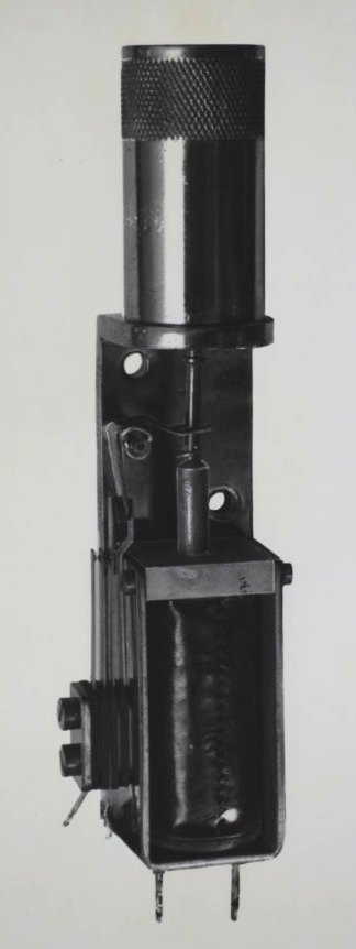
Dashpot relay
Rotary Switch, Line Finder and Selector type
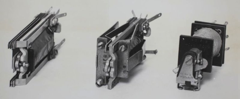
STC Relays
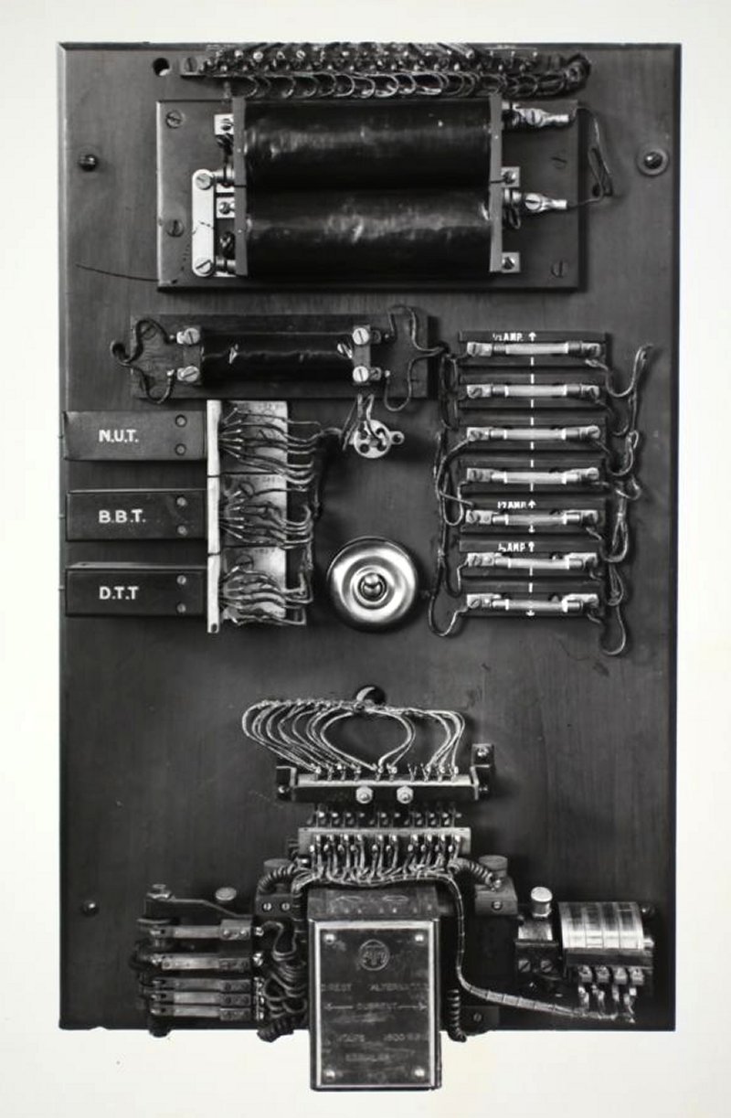
Ringing Machine Panel
|
|||||||
Last revised: February 12, 2023FM |