|
Frames and Covers, Carriageway No. 4
For use only on carriageway Joint
Boxes No. 4, in grass
verges, pavement crossovers, service roads and lay-bys.
Fitted with a Covers, Carriageway, No. 4.
Made obsolete in 1984.

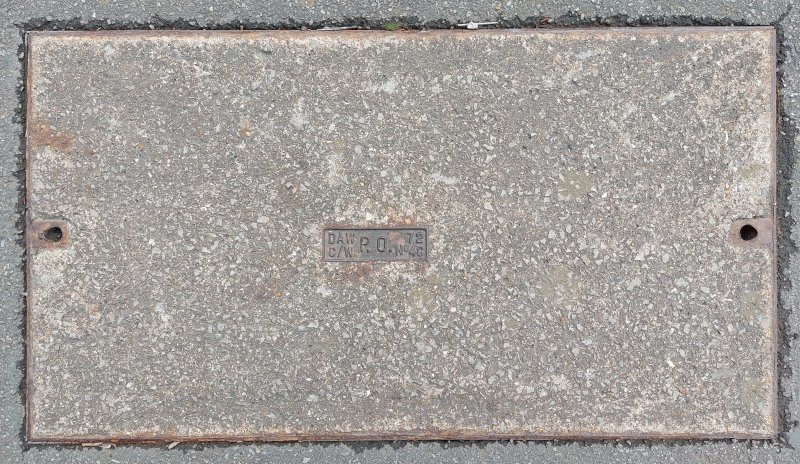
Covers, Carriageway No. 4
Covers, Carriageway No. 4
ENGINEERING INSTRUCTIONS
LINES
Underground
C3060
Issue 2, April 1970
FRAMES AND COVERS, CARRIAGEWAY, No. 4
General
Where traffic conditions do not justify the use of the heavy
duty frames and covers, a lighter and less expensive frame and cover should be
fitted. This instruction describes one of the frames and covered designed for
this purpose, the method of installation and conditions of use.
CAUTION
2 Freeing of Covers
In no circumstances should an attempt be made to
lift
a cover manually without first ensuring that the cover is 'free' in the frame as
failure to do this can lead to back injuries. The method of breaking the seal of
tight covers is described in TOOLS AND TRANSPORT, Hand Tools, K 1005.
3 Conditions of use
These frames and
covers must only be installed in
roads carrying service traffic to houses and in pavement cross-overs for
vehicular traffic to garage entrances. They may also be used to replace Frames
and Covers, Footway, No. 4, installed prior to a garage entrance being
constructed. If a smaller footway joint box exists in a proposed or existing
garage entrance, it may be demolished and replaced by a No. 4 carriageway joint
box.
4 Description
The frame and cover are
of mild steel construction with a
zinc sprayed finish. The general design and construction is similar to the
pressed steel frames and covers already in use for footways, except that the
cover is formed from sheet steel with the edges bent up to form a tray with
welded corners. The cover is concrete filled at the manufacturer's works. The
frame and cover are illustrated in Fig. 1.
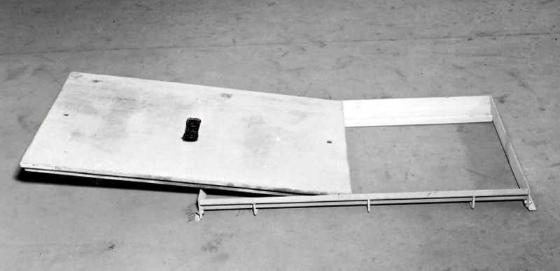
FIG. 1
5 Weight and size
The weight of the frame is 15lb. and that of the cover
is 160lb. The clear opening size is 3 ft. x 1 ft. 6 in.
6 Loading capacity
These frames and covers are capable of withstanding
a reasonably heavy static and rolling wheel load, but are not suitable for use
in
carriageways carrying frequent and fast-moving traffic. The conditions laid down
in par. 3 concerning location of installation must be strictly observed as
failure of a cover in service could have serious consequences.
7 Materials for installation. The
coarse aggregate should consist of well graded 3/8in. down, hard natural stone. The fine aggregate should be clean,
sharp natural pit or river sand with a silt content not exceeding
5%. The cement should be
rapid-hardening Portland cement to B.S. 12, or high-alumina cement to B.S. 915.
For replacement work it may be more convenient to use high-alumina cement, but
for new work rapid-hardening Portland cement will generally be found to be
suitable. There is no technical objection to the use of ordinary Portland
cement, but other factors will generally justify the use of a rapid-hardening
cement.
8 Mixes
(a) Concrete
Cement (all types) - 1 part by volume.
Fine aggregate - 2 parts by volume.
Coarse aggregate 3/8 in. down - 3 parts by volume.
(6) Mortar
Cement (all types) - 1 part by volume.
Fine aggregate - 3 parts by volume.
The water content should be the minimum necessary to give a workable mix and
generally a water/cement ratio of 0.55 by weight will be satisfactory with
the mix specified.
When concrete or mortar is mixed manually, mixing should be done on boards
or a platform, not directly on the street paving or carriageway. The
platform should be large enough to allow the material to be moved completely
from one position to another on the platform in the course of turning over.
Surplus or condemned materials should be removed from the working site, care
being taken that no materials are left to be washed into drains or sewers.
9 Installation
(a) New work
The joint box should be constructed as shown on Drawing CN 1815 with the top of the joint box wall
3* in. below the carriageway surface. Before attempting to set the frame and
cover, they should be examined for possible damage in transit.
The top of the joint box wall should be moistened with water and a 1/2in.
layer of mortar trowelled over the entire surface. Additional mortar should
be placed on this so that it conforms approximately to the contour of the
frame section to enable a proper bedding to be obtained. The frame should
then be placed in position and lightly tapped with a piece of wood so
that excess mortar is forced out, until the frame projects approximately
1/4in. above the carriageway surface. Excess mortar between the frame
and the inside of the joint box should be neatly struck off. The cover
should be placed in the frame using two Keys, Joint Box No. 2 and the whole
assembly lightly tapped with a piece of wood until the cover is level with
the carriageway surface. Any tendency for the cover to rock should be
corrected by
inserting additional mortar under the low corner of the frame until the cover
seats satisfactorily. The mortar should be neatly trowelled off around the
outside of the frame so that it slopes away from the top edge. In unmade roads
it is desirable to protect the frame by enclosing it with a 2 in. surround of
concrete of the mix defined in par. 7.
(b) Replacement of Frame and Cover, Footway, No. 4
It will sometimes be
necessary to replace this type of frame and
cover when an existing footway joint box becomes sited in a garage entrance or a
pavement cross-over is constructed. The existing frame should be removed and old
mortar on top of the joint box cleaned
off. The carriageway frame and cover is then fitted in a similar manner to that
described in par. 9 (a), the amount of mortar used being adjusted according to
the site conditions.
10 Opening to traffic
The completed
joint box and its associated frame and cover should not be exposed to
traffic until the following times, depending on the cement used, have elapsed:-
-
Portland cement 7 days
-
Rapid-hardening Portland cement 3 days
-
High-alumina cement 24 hours
11. Removal and replacement of covers
These covers can be slid out in either
direction along the long axis of the cover using a Key, Joint Box, No. 2. Before
replacing the cover any foreign matter in the frame grooves should be removed.
The cover is replaced by inserting a Key, Joint Box, No. 2 in the end farthest
from the joint box and sliding the cover forward along the grooves in the frame
until it is fully seated.
|