UNDERGROUND CONSTRUCTION
|
||||||||
|
These are produced in two styles, the "Unit Type" and the "Unit Type Light". The difference is that the "Light" type are of lighter construction, the depth being 3.75" compared with 6" for the standard Unit Type.
The "Light" types are for use in grass verges, pavement cross-overs, service roads and lay-bys only.
Keys, Joint Box No. 2 are used to remove the covers.
Frame A with Cover ENGINEERING INSTRUCTIONS
Unit Type
1. General
This Instruction describes the standard method of setting Frames and Covers, Unit Type. However, in a situation where repeated failures have been experienced or where a minimum of 24 hours setting time using High Alumina cement cannot be allowed, this method should not be used and C3907 should be followed. 2 Identification 3 Component Parts
Unit 'A' comprises:-
2 Frames and Covers, Unit, End Frames 2 Side 1 Covers
Unit 'B' comprises:-
Unit 'C' comprises: -
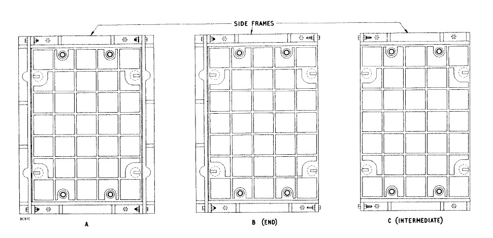
2 Frames and Covers, Unit, Side Frames 1 Covers This makes it possible to assemble frame sections to hold more than one cover.
4 Sizes Two Frames and Covers, Unit, 'B' and a Frame and Cover, Unit, 'C' bolted together (Fig 3), give a clear opening of 2ft 9 in. x 2ft in. for use on JRC 11, JBC 11, JRC 14, and JBC 14 joint boxes.
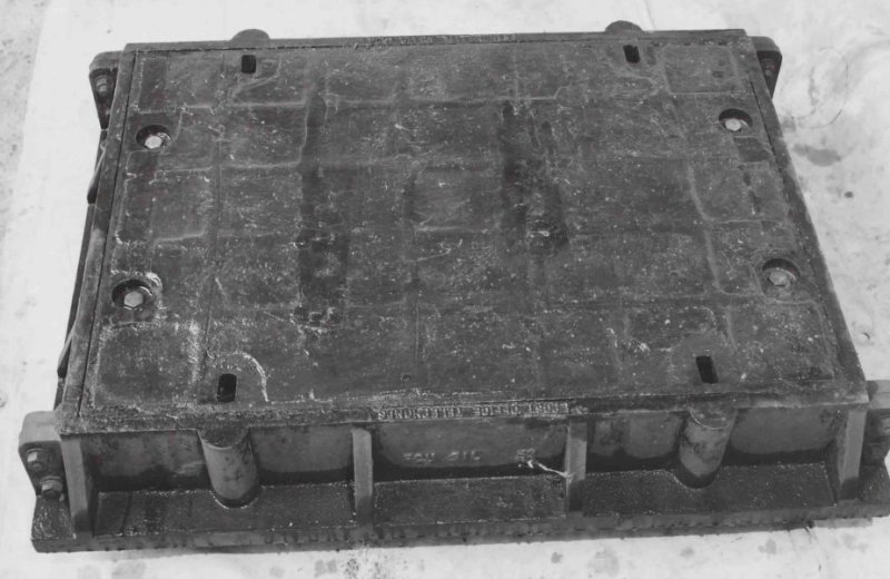
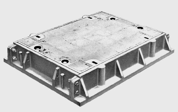
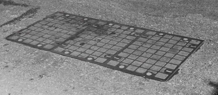
Fig 1. Frame and Cover, Unit, 'A'
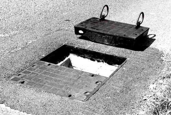
Fig 2. Two Cover Installation
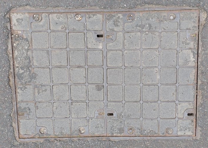
Fig 3. Three Cover Installation 5 Frames and Covers 6
Concrete mix The water content should be the minimum necessary to give sufficient workability. 7
Concrete materials for installation When concrete or mortar is mixed manually, mixing should be done on boards or a platform, not directly on the street paving or carriageway. The platform should be large enough to allow the material to be moved completely from one position to another on the platform in the course of turning over. Surplus or condemned materials should be removed from the working site, care being taken that no materials are left to be washed into drains or sewers. 8
General precautions to be taken before
installation
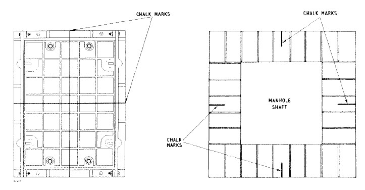
In all cases the top of the shaft must be 8in. to 8.5in. below the carriageway surface and before any attempt at installation is made this distance should be checked. As the opening will be obscured when the frame and cover is placed in position, mark the centre lines of the frame and cover with chalk on both the cover and the surrounding carriageway or top of the man-hole roof as shown in Fig 4. Set up the shuttering on the inside of the opening, projecting between 2in. to 2.5in. above the top course of bricks. Take care not to exceed 2.5in. as the shuttering may foul the frame and cover.
Fig. 4. Positioning Frame and Cover, Unit 'A' Remove the frame-levelling screws and replace them with the heads
uppermost. Then screw down the frame-levelling screws so that the
threaded portions project about 3 in. below the underside of the frame.
Then carefully lower the frame and cover onto the opening, using
suitable lifting gear such as a Hoist, Portable, Hand with a Chain, Sling, 4 Leg
(see T & T, Mechanical Aids, B1010). Adjust the levelling screws to bring the
cover level with the adjacent carriageway surface. If the frame and
cover is part of a new installation, set up shuttering around the frame and
cover so that the inner face of
the shuttering is 6in. away
from the inner vertical face of
the frame. For replacement purposes this will not be
necessary as the excavation will
form the shuttering. Then place concrete in the space between the out-side
shuttering and frame.
Build up a head of
concrete and then thoroughly consolidate with a
Vibrator, Concrete, Electric, so
that the concrete flows
under and around the frame. Bring up the
finished level of concrete
to within 2 in. of the top of the
frame. The installation must then be left undisturbed and lamped
off for the following periods:- After these minimum times have elapsed remove the inner and outer shuttering and do any necessary making good to the concrete inside the frame with a cement mortar made with the same type of cement as that use for installation. Thoroughly clean the frame seating using a dry rag and the cover seating using a rag moistened with paraffin. When the cover seating is thoroughly clean and dry, coat it liberally with Compound No. 14. Apply the compound to the cover seating's only. In very warm weather the compound may be sufficiently liquid to be trowelled onto the seating's. If it is not, small lumps of the compound should be placed at intervals on each seating of the upturned cover. Direct heating by means of a Torch, Propane or similar equipment will cause the compound to melt and flow evenly over the whole area of the seating. The minimum amount of heat necessary should be used because if the compound is overheated, unpleasant fumes will be given off. The tin containing the compound should never he heated as this can be dangerous. Replace the cover and, except where the covers are to be bolted
down, seal off the holes left by the holding-down bolts with a packing
of cotton waste and cement mortar or asphalt, whichever is the most
convenient. An interim reinstatement should be made but before exposing
the installation to traffic a minimum period after completion of the
concreting must elapse, as follows:- In very cold weather 5 days should be allowed for rapid-hardening Portland cement. 10 Multi Cover Installation
Fig 5. Frame and Cover Units 'A', 'B' and 'C'
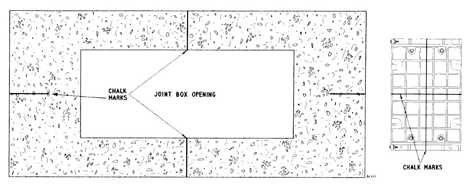
(a) 3 Cover installation. Remove the nuts and bolts from the
exposed jointing faces of the side frame members and store safely for
later use. As with the single cover installation, mark the centre lines
on the covers and on the top of the joint box with chalk, the transverse
line being the centre of the 'C' unit (see Fig 8). Set up the shuttering
on the inside of the joint box with struts to prevent the shuttering
bowing under the weight of the concrete. Check the cover and frame bolts
as detailed in paragraph 8 and reverse the levelling screws so that their
heads are uppermost and about 3 in. of the threaded portion projects
below the frame. Place the 'C' unit in position, taking care not to
disturb the shuttering, and adjust the levelling screws so that the unit
is approximateley level with the surrounding surface. Lift each 'B' unit into
position and similarly adjust the height with the levelling screws.
Insert the frame-securing bolts into the abutting frame sections and bolt the units loosely together. With the aid of a straight edge or cord line, adjust the levelling screws so that all the covers are level with the surrounding carriageway. Fully tighten the frame bolts. As detailed for a single cover installation, place concrete around the frame and, after the minimum time has elapsed, treat the cover seatings with Compound, No. 14. An outer ring of shuttering will not normally be necessary in the case of a joint box. Finish off with an interim reinstatement and, as for single cover installations, allow the appropriate period to elapse before opening up to traffic.
Fig 6. Positioning a Three Cover Installation (b) 2 Cover installation. 2 cover installation is identical to that for 3 covers except that the 'C' unit is omitted and the transverse datum line is at the junction of the 2 'B' units. 11 Removal and replacement of covers 12 Ventilation 13 Weight of frame and cover units 14 Bolting down covers
Difficulty in fitting the cover holding-down bolts can be avoided by
cleaning the thread in the holes of the frame seating using a new bolt
with a liberal application of oil before replacing the cover. Should the bolt holes be choked with silt and small stones causing the
bolts to '-bottom', remove the debris via the specially
provided holes on the inside edge of the frame seating. Earlier issues of Frames and Covers, Unit Type were
not provided with these clearance holes and a small space should be
carefully chipped away from the concrete bed immediately under the bolt
holes to give the same facility.
15 Renewal of polythene seats 16 Frames and Covers, Unit Type (Light)
Keys, Joint Box, No. 2 (T & T, Hand Tools, K1005) may be used to remove
and replace these covers.
|
||||||||
Last revised: July 24, 2025FM2 |
||||||||