GPO Vehicles | |||||||||||||||||||||
These GPO vehicles were fitted with front and rear wings made of rubber.
P.O. ENGINEERING DEPT. MOTOR TRANSPORT 1. General
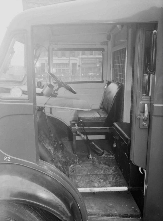
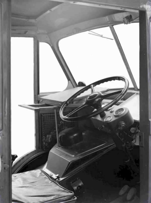
3. Cab
Situated behind the driver and let into the top portion of the wire mesh screen is a two-compartment locker equipped with sliding doors. One compartment is intended for personal effects and the other, together with a wire mesh container mounted adjacent to the table, for E.I.s., books, papers, etc.
The Post Office Electrical Engineers Journal New 10-cwt.
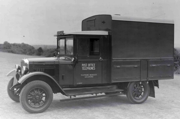
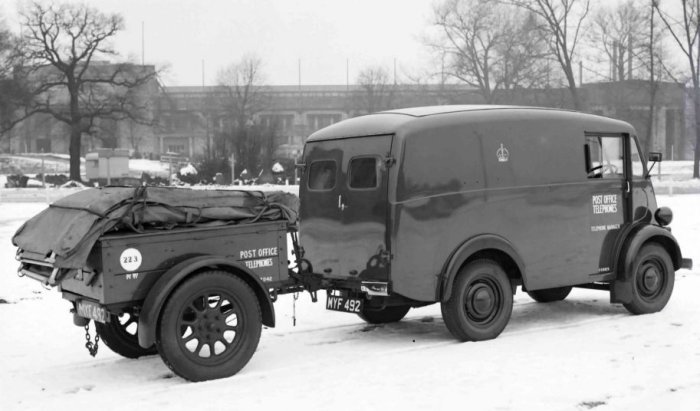
Utility Vehicle This article describes a new 10-cwt and shows the prototype vehicle, which has front wheel steel wings. It is a Utility vehicle for use on external construction work in circumstances where the standard 1-ton Utility vehicle is unnecessarily large (see picture below). The new vehicle is a Morris Commercial "J" type as used in the postal fleet, but modified to meet engineering requirements. Introduction. The present standard l-ton Utility vehicle was introduced as a result of a recommendation of the Committee on Engineering Transport Efficiency in 1935. The recommendation was to abandon the then existing 1-ton General Utility vehicle, and to incorporate some of its features in the 1-ton Jointer's vehicle which would then serve as standard for 2-men or 3-men working parties including jointers. At the same time the 15-cwt. Jointer's van, the 15-cwt. Fitter's van and the 10-cwt. Trojan van were withdrawn from engineering use; thus five individual types of vehicle were merged into one.
Fig. 1 - The 1-ton Utility Vehicle Except for comparatively minor modifications the 1-ton Utility vehicle has served for nearly 20 years, covering a wide range of duties for overhead, underground and installation parties, and is a tribute to the wisdom of those who made the decision and to the designers of the original vehicles. Because of the facilities incorporated in its design to meet the varying requirements of the duties involved, the vehicle is, of necessity, much larger, heavier and more expensive than one with a less extensive range of use, and it is inevitable that many of the facilities provided, e.g. for carrying a long ladder and wiring drum, may never be used. Certainly many such vehicles never tow a trailer. At the present time the engineering fleet includes approximately 1600 1-ton Utilities (about one tenth of the fleet), and it was considered that the number was sufficiently large to justify a review of the situation with a view to reducing motor transport costs and securing other advantages. It should be mentioned that during the war the 1-ton Utility could not be
obtained; accordingly the 8-cwt. van type 1 was in many cases used as an
alternative. In spite of its limitations this smaller vehicle proved reasonably
suitable for many two-men parties where the longer types of ladder were not
required, and in fact many of these vehicles are at present in use by jointer's
although the housing of the tents presents a problem which cannot be Morris Commercial "J" Type 10-cwt. Van
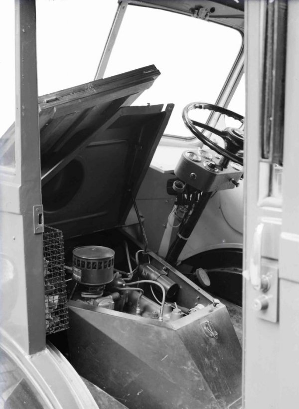
Fig 2. - The new 10-cwt Utility Van With the introduction of the "J" type Morris van to the postal fleet as a replacement for the 100 cu.ft. van, which was of course commercially the same type as the engineering 8-cwt. van type 1, the Construction Branch was asked to consider the use of this vehicle for engineering purposes. At first sight the Morris "J" did not appear particularly attractive; the vehicle was unsuitable for a ladder carrier on the roof, firstly because the roof was rather high, and secondly because there was a possibility of instability with a ladder mounted in that position. It was decided, however, that by limiting the maximum size of ladder to be carried to that of a Ladder, Extension No. 5, which is 8ft. 4in. in length (closed), it would be possible to house the ladder on the floor of the vehicle, an arrangement which offered considerable advantages in both vehicle stability and ease of loading, unloading and securing the ladder. Further, at this stage it was decided that the vehicle not only offered advantages as a superseding type for the 8-cwt. van type l, but also had distinct possibilities as a superseding type for many 1-ton Utilities. A standard Morris Commercial "J" type 10-cwt. van was therefore made available by the Motor Transport Branch for modification to produce a prototype engineering vehicle. The "J" type 10-cwt. van for postal work can be readily recognised by the prominent feature of the sliding doors. This feature offers obvious advantages in both use on the roads and in garaging space, in that it provides adequate openings for entering and leaving the cab on both near side and off side without any of the disadvantages associated with the sweep of the door necessary in the hinged type: and, although the doors of a postal van may open many more times in a day than the engineering counterpart, the introduction of the sliding door to engineering vehicles will undoubtedly bring distinct advantages in use on the job and in garaging. Modifications to meet Engineering Requirements The forward end of the ladder when in the tunnel extends to a position immediately below the driver's seat; the Morris Commercial seat was, therefore, removed and replaced by a Departmental standard seat mounted on steel bearers, with a sheet steel panel to form a front stop for the ladder. The near side of the seat mounting was left open to give access to the ladder from the front end should this at any time be necessary, and the off side was partly screened to ensure unobstructed access to the off side step. The seat is adjustable forwards and rearwards in the usual manner and is of the same height, and in exactly the same position as the Morris Commercial standard seat. To facilitate the housing of the tent sections and to provide a comfortable passenger seat, the wire mesh screen has been stepped. This allows the passenger seat to be set back and, by partly covering the step well, adequate leg room for the passenger and an easy step from the near side of the vehicle are provided. Both steps, near side and off side, are therefore alike, and access to either seat is possible from either side of the vehicle. Further, there is possibly an advantage in the setting back of the passenger seat in that the driver's view when looking to the left is less likely to be obscured by the passenger. The fitting of the false floor necessitated the repositioning of the vehicle battery, which in its normal position under the main floor of the vehicle on the off side, would have been inaccessible because of the false floors supports. It was, therefore, removed and repositioned under the passenger's seat, where ready access to the battery and master switch is available by simply tipping forward the passenger seat on its hinged mounting. Also, part of the space available under the passenger seat has been profitably used for stowing the smaller vehicle tools in a lock-up compartment.
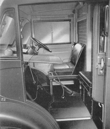
Fig.3 - Details of construction of the false floor To provide lock-up accommodation for the books and papers necessary for the Department's work, a locker is incorporated in the upper portion of the wire mesh screen immediately behind the driver. This locker has two sliding doors and is partitioned to provide two compartments. A table was designed to be easily removable when major maintenance is necessary to the engine, and to fold back with the engine cover to give ready access to the engine for normal maintenance operations. The table top also folds on itself, and when the hinged flap is brought forward it provides a writing table, or if desired a meal table. This table fits into the space immediately above the engine cover (Fig. 4), being secured in position on hinged brackets fitted just below the near side wind screen and supported on a folding leg, the lower end of which fits into a slot in the engine cover. The hinged flap of the table top is additionally supported, when open, by two sliding arms housed on the under-side of the fixed half of the table.
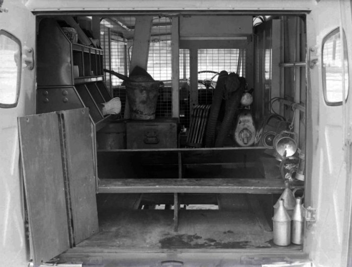
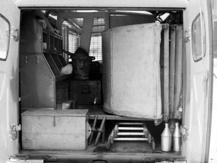
Fig. 4 - View inside driving cab showing the writing table The fittings inside the body are simple and consist of two bins mounted one above the other as compartments on the near side of the vehicle, providing accommodation for small items of stores and tools. The under floor space on the near side can, if necessary, be used to stow digging tools, a pair of five-tread folding steps, pruning rods, tent seats and stretcher bars, and tarpaulins, according to requirements. The space immediately behind the near-side under floor space conveniently accommodates a jointer's toolbox. A typical layout of tools, stores and equipment, in which a jointer’s kit with motor pump and lighting set is included, is shown in Fig. 5.
Fig. 5. - Typical Layout of Equipment in Vehicle Two lights inside the vehicle, one in the body and one in the cab, controlled by a switch beside the driver's seat, provide artificial light, and two coat hooks on the screen behind the passenger seat complete the internal fittings. The rear bumper bar has been arranged for the attachment of a towing hitch for the purpose of occasionally towing a trailer tool cart, which is well within the capabilities of the vehicle. Towing is confined to trailer tool carts only, and it has, therefore, been decided that the towing hitch shall only be fitted on request when it is considered essential to provide the facility. Conclusion On present-day costs it may sometimes be possible to justify the use of such a vehicle in place of a trailer tool cart, considering the manhours lost on divergent journeys and in waiting to be picked up, which often occurs when two parties are at work, one with a trailer tool cart being dependent on another with a 1-ton Utility. Here two Morris "J's" may well provide a more economic arrangement as well as bringing the not inconsiderable advantage of complete and independent mobility to both parties. In garaging space the vehicle also offers some advantages in that it is estimated that three of these vehicles can be garaged in the space required for two 1-ton Utilities, a factor which is of appreciable importance in these days of restricted garaging space. It is emphasised that the vehicle is not intended to supersede the 1-ton Utility as a type generally. It cannot do this. If it is necessary to carry a ladder longer than the Ladder, Extension No. 5, or a pay-load greater than 10 cwt. including driver and passenger or additional passengers, the vehicle is unsuitable.
|
|||||||||||||||||||||
Last revised: August 07, 2025FM3 | |||||||||||||||||||||