| Make |
Morris |
| Model |
Minor "O" series (Morris) |
| Type |
Minor Van Type 3 (Morris) |
| Body Builder |
|
| Use |
External Maintenance |
| Registration Number |
NLW 952 |
| Fleet Number Ranges |
U59523 to U59524 (NLW 583 - 584) 1953
U59725 to U59881 (NLW 843 - 999) 1953
U58882 to U59999 (NXO 252 - 369) 1953
U66000 to U66275 (NXO 370 - 645) 1953
U66276 to U66363 (OXN 362 - 999) 1954
U67364 to U67525 (OYF 1 - 162) 1954
U67758 to U68036 (PGO 120 - 398) 1954 |
| Date of picture |
February 1954 |
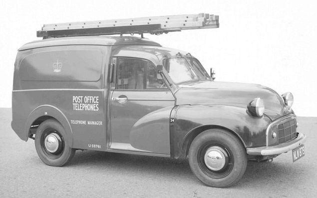
General description and facilities
This van supersedes and is interchangeable with Minor Vans Types 1 and 2.
The cab has two seats to accommodate one passenger and the driver and.-is
separated from the vehicle body by a wire-mesh partition. A roof ladder rack
is provided for the transport of a Ladder, Extension, No. 4A or 5. Steps,
Folding, 5-tread may also be carried within the body immediately under the
roof of the vehicle, using the securing straps. The standard vehicle is
fitted with two internal racks (unit A), one either side of the body, for
the accommodation of tools and stores. Additional racks (units B and C) are
available and may be mounted above the unit A racks. The vehicle is intended
for use on duties that normally require one man only and where the weight of
tools and stores to be carried does not exceed 5 cwt. If however a passenger
is carried, the vehicle load must not exceed 4 cwt.
Taken from - ENGINEERING INSTRUCTIONS, TOOLS & TRANSPORT, VEHICLES N1003
(Issue 1, 1.6.67)
This is the first variant of the Morris Minor van. NLW 583 and 584
are prototypes.
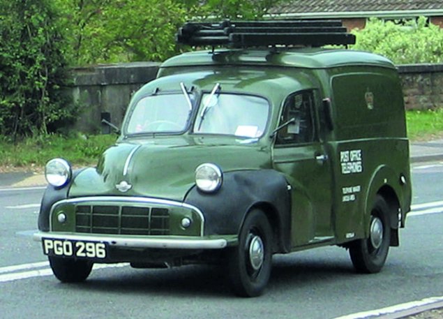
39,417 of these were supplied to the GPO up to October 1969.
PGO 315 was the last vehicle to have rubber wings. Metal wings were
specified from PGO 316 onwards.
See also NLW 879

This model has frog eye headlamps, due to the rubber wings,
and a
drivers windscreen that opens


P.O. ENGINEERING DEPT.
ENGINEERING INSTRUCTIONS
TOOLS & TRANSPORT
VEHICLES
B 3606
Issue 1, 25.2.56
MOTOR TRANSPORT
Minor Van, Type 3
1. General
This Instruction describes the Minor Van, Type 3. The types of duties for which it is intended are given in B 3550. It supersedes and is interchangeable with Minor Vans, Types 1 and 2.
2. Description
A general view of the vehicle is shown above. The overall dimensions are: length 12 ft., width 5 ft. and height 5 ft. 9 ins. The body of the vehicle is of welded pressed-sheet-metal construction, mounted on a Morris chassis. Cab and body are separated by a wire-mesh partition
- as shown in Figs. 2 and 3 - to enable the body to he locked (see par. 12) without restricting access to the cab. Accommodation is provided externally for an extension ladder and internally for a step ladder, pruning rods, tools, stores, E.I.s, etc.
3. Ladder Carrier
A horizontal type of ladder carrier is provided on the roof for a 'Ladder, Extension, No. 4 or No. 5.' At the rear end of the carrier,
a roller is fitted to facilitate the placing and removal of the ladder. The roller should be oiled periodically to ensure smooth and easy rotation. The ladder should he secured at the front and rear by the straps provided for this purpose, and should be so positioned that the ladder does not overhang the rear of the vehicle. To allow for the difference in the bottom rung position on the various types of extension ladders Nos. 4 and 5, two sets of staples for anchoring the ladder securing straps are fitted on the ladder carrier. Only one extension ladder of the specified type may be carried on the ladder carrier and, except for the special provision mentioned in par. 10, nothing else may be carried on the roof or on the ladder carrier.
4. Cab
Seats in the cab provide for an occasional passenger in addition to the driver, the driver's seat being adjustable. Two wire-mesh containers
- for E.1.s, log sheets, diagram folders, works and other papers - are mounted on the wire-mesh partition, one container being positioned behind each seat. The vehicle tool box is located immediately behind the passenger's seat.
A hat and coat hook is provided in a central position on the partition behind the seats. The fire extinguisher is accommodated in the cab.
5. Step Ladder Accommodation
'Steps, Folding, 5-tread' (see par. 6) may be carried within the body where they are secured, in a central position immediately under the roof (Fig. 3), by two webbing straps. The aperture at the top of the partition, through which the steps must pass, is provided with a separate hinged wire-mesh panel as a security measure when steps are not carried (see Fig. 2). 'ro clear this aperture for the accommodation of steps, only the top fastening of the wire-mesh panel should be undone. The panel will then hinge downwards and can be stowed behind the spare wheel. When the
folding steps are being inserted, keep the step treads uppermost and place the top of the steps on the lower edge of the aperture in the dividing partition; raise the bottom of the steps as near to the horizontal as possible and push them forward until the top of the door framing can be cleared; fasten the safety chain provided, to support the bottom of the steps while the rear strap is being fastened; pass the rear strap round the safety chain as well as the bottom step tread and fasten the strap tightly, ensuring that the steps are drawn to the rear as far as possible; then fasten the front webbing strap. The foregoing procedure should be reversed to remove the steps.
6. Requisitions for 'Steps, Folding, 5-tread' for use on these vans should be endorsed 'Folding tread type required '.
 |
| Fig 4 |
7. Rack Units
Accommodation for stores and tools is provided by rack units which can be fitted on each side of the interior of the body and which are illustrated in Fig. 4. When the van is supplied, A Units only are fitted (Fig. 2). These units are positioned to leave space between the body ribbing and the back of each unit, for the convenient stowage of large-diameter coils of wire. Such coils of wire should be fastened to the vehicle ribs to avoid their movement in transit. B and C Units are. available as optional fitments, being mounted on top of the A Units and secured by brackets. The use of a B or C Unit removes the wire-carrying facility from the side of the body concerned.
If additional clear floor space is desired, one or both A Units can be moved back against the body ribs. Where an A Unit is set back in this way, the wire-carrying space behind it is eliminated and it is no longer possible to mount an upper unit on that side of the vehicle. Only two bolts are used to secure the feet of each A Unit in its backward position and the back of each unit should, therefore, be secured to the body ribs by one of the short bolts recovered from the original floor fixing. Spare bolts and packing pieces should be retained with the vehicle tool kit against a future change in the van's duties.
If, on certain duties, less rack accommodation than the initial two A Units is required and extra clear floor space
if necessary, one or both A Units may be removed (see also par. 9).
Fig. 3 shows a layout of a typical dual maintenance officer's load. Owing to the many variations in the circumstances under which Minor Vans may be employed, it is not practicable to lay down any specific layouts. Much must be left to the initiative and good sense of each officer concerned in making the best use of the facilities available. The principle of keeping heavy items on the lowest level possible should always be observed. Telephone instruments, spare parts, cords, small stores, etc., should be carried in suitable cartons to prevent chafing and rattling and every effort should be made to utilize the special containers available for certain items, e.g. ' Gloves I.R.' and dials.
 |
| Fig 4 |
8. Supply of Additional Rack Units
When additional units are required, requisitions (A 1063) for 'Minor Van Fitting Unit A, B or C' should be
forwarded to the Supplies Dept. On receipt of the additional items, an appropriate entry should be made on the vehicle tool list (A 1112).
 |
| Fig 4 |
9. Recovery of Rack Units
Units surplus to requirements should be returned (direct) to the Supplies Dept., and the items deleted from the vehicle tool list. The special nuts (Simmonds Elastic Stop Nuts) provided for the set-screws securing the component units together should not be used for other purposes but should be secured to their relevant units and returned with the brackets to the Supplies Dept.
10. Pruning Rods
When pruning rods are carried, they may be placed on the floor of the vehicle, their front ends being passed through the aperture provided for this purpose in the dividing partition (Fig. 3). The rear of the set of pruning rods can be secured to an anchorage set in the vehicle floor beside the rear support of the off-side A Unit. Alternatively, they may be carried on the ladder carrier by means of brackets bolted to the near-side of the ladder carrier (see M 0048).
11. Maximum Permissible Load
The maximum load that a Minor Van, Type 3, may carry without any fittings is 646 lb. (apart from the
weight of the driver, which has been taken at 168 lb). Hence, if a passenger (average weight 168 lb.) is carried when a pair of A Units (each weighing 34 lb.) is fitted, then the total weight of tools, stores, etc.. must not exceed 410 lb. The B and C Units each weigh 26 lb. and the load carried must be reduced accordingly when these units are fitted.
A periodical examination should be made by the driver to ensure that surplus items are not carried and that the maximum permissible load is not exceeded. A simple check can be made by weighing the van in its moving condition, i.e. with driver, passenger (if carried), stores, tools, racks, petrol, oil, etc. The total moving weight must not exceed 24 cwt. Any weighbridge charges involved should be passed to 'Freight and Cartage '.
12. Locking Arrangements
Cab and rear doors are equipped with standard FA 600 Series locks to enable the contents to he safeguarded when the vehicle is left unattended for short periods. For extended absences additional security can be obtained by padlocking the rear doors. A hasp and staple are fitted to the rear doors for this purpose. Tile vehicle tool box is also equipped with a hasp and staple.
Padlocks l.25 in. are the correct padlocks for use on this class of vehicle.
(NOTE:- Padlocks 1.25 in. are sometimes of the spring self-locking type; to prevent the accidental locking of keys inside the van body, it is recommended that the padlock keys should not all be carried together.)
A spring clip is fitted on the rear door to prevent chafing by the padlock.
13. The spare wheel is mounted on the rear of the dividing partition.
14. Re-enamelling and Retouching
The outside of the van has a synthetic enamel finish. Attempts to retouch any scratch or damaged part should not be made by the staff using the vehicle: work of this nature is undertaken by the Workshop Supervisor/ Mechanic-in-Charge when necessary and during periodic overhauls.
15. Modification to ladder carrier
Unless an extension ladder is properly secured on the ladder carrier the ladder is likely to work over to one side of the carrier. With Type 3 Minor Vans, of serial numbers U 81931 or below, carrying aluminium Ladders, Extension, No. 4 of an early pattern of exceptionally narrow width, lateral movement can result in the ladder stile slipping off the inside edge of the horizontal portion of the carrier woodwork at the forward end, on to the metal cross-member supporting the forward end of the carrier. Rapid wear of the ladder stile ensues.
If such difficulty is encountered, a request should be made to the R.M.T.O., via the Workshop
Supervisor/Mechanic-in-Charge, for the ladder carrier to be modified by. widening the wooden members which support the ladder stiles, from 3.75 in. to 4.5 in.
The ladder racks on Type 3 Minor Vans with serial numbers above U 81931 already embody the 44 in. wide wooden members to support the ladder stiles. Later issues of aluminium Ladders, Extension, No. 4 (and Ladders, Extension, No. 4A) are specified to be of a minimum width which does not give rise to the
difficulty.
16. Towing
Minor Vans, Type 3, are not suitable for towing any type of trailer or for use as a power unit, and officers are forbidden to use or attempt, to use the vehicle for these purposes.
17. Signwriting
Standard inscriptions for signwriting are given in C 0015.
18. The speed limit for this vehicle is 30 m.p.h.
References:- B 3550, C 0015, M 0048
|