AMPLIFIER No. 109 | ||||||||||
|
This is a small, variable gain amplifierwhich operates
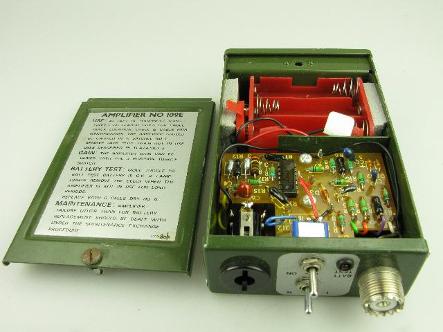
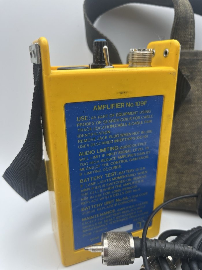
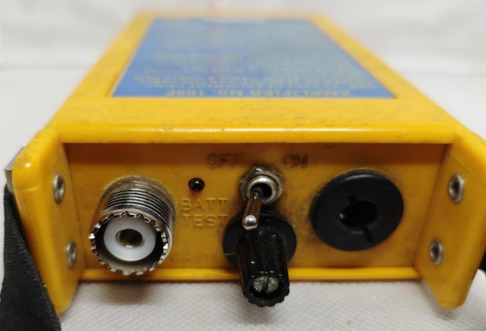
from an internal dry battery. The maximum gain is approximately 70dB. Mounted on top of the case are two toggle switches, a UHF, coaxial input socket and an output jack together with a battery state indicator lamp. One switch has 3 gain settings, Low (L), medium (M) and high (H). The other has OFF, ON and BATTERY TEST positions. The output jack receives the plug of the Receiver Headgear No. 16T. Removing the plug disconnects the internal battery. The coaxial input socket connects with the Cord Connecting No. 2/12A which nay be connected to the Search Coil No. 2B or the Probe No. 5B. Earlier versions of the amplifier e.g. Amplifier No. 109D will only have an edgewise gain control potentiometer with integral switch, instead of the advanced features of the amplifier No. 109E NB: The following items of equipment will be obsolete when stocks are exhausted owing to the changeover to the latest versions of the Amplifier, Search Coil Probe and Cord: Amplifiers No. 109A, B, C, Search Coil No. 2A, Probes No. 4 and 5, Cords Test No. 2/72A, and No. 2/112A. During the changeover period, amplifiers with the screw-thread UHF socket may be used with existing cords, probes and search coils if an Adapter Coaxial No. 72A is used.The Amplifier may be carried in a Satchel No. 4 if the restraining strap on the satchel makes operation of the toggle switches difficult, it should beremoved. Used for cable track location and identification in conjunction with an Oscillator No. 87. An Aerial No. 32A, which is fitted with a U.H.F. plug can be used with the Amplifier No. 109 for fault location on overhead cabling. Early versions used a Battery, Dry No 23, which was an Ever Ready 1289 or an 3LR12 (4,5v). Later versions used six Cells, Dry No. 26. A Satchel No. 4 was available for containing the Amplifier. Part of Tester No. 132 and Tester No. 137A. Amplifier No. 109A To be requisitioned separately as required:- 1 x Battery, Dry No. 23. 1 x Plug No. 420 with Cord, Instrument 2/138AB, 54". 1 x Receiver Headgear No. 16T, Black. 1 x Satchel No. 4. Amplifier No. 109E onwards To be requisitioned separately as required:- 1 x Receiver Headgear No. 16T, Black. 1 x Plug No. 420 with Cord, Instrument 2/138AB, 54". 1 x Adapter, Coaxial No. 72A. 6 x Cell, Dry R6. 1 x Satchel No. 4. Drawings - CD2646, 90811, 90850 and 91141. Circuit Diagram - SA9123. Specification - D2537 (No. 109C).
|
||||||||||
Last revised: December 04, 2025
FM
| ||||||||||