P.O. ENGINEERING DEPT.
ENGINEERING INSTRUCTIONS
MISCELLANEOUS
TIME
B 1125
Issue 3, 22.9.59
MECHANICAL CLOCKS
Clock No. 17A - Description
1. General
 The Clock
No. l7A is used with associated apparatus (see Diagram AT 2041) to give half-hourly audible warnings in telephone exchange
switch rooms of nine or more working positions during traffic call-counts.
These clocks operate single stroke bells (Bell No's 48A or 27A) for "peg counts".
The bells could be switched on and off by means of a Switch, Tumbler No. 1. The Clock
No. l7A is used with associated apparatus (see Diagram AT 2041) to give half-hourly audible warnings in telephone exchange
switch rooms of nine or more working positions during traffic call-counts.
These clocks operate single stroke bells (Bell No's 48A or 27A) for "peg counts".
The bells could be switched on and off by means of a Switch, Tumbler No. 1.
These would only be fitted at exchanges with five or more
positions.
In new exchanges fitted with master clocks (Clocks No. 36) Clocks
No. 62A are used in place of Clocks No. 17A (see B 1342).
2. Description of clock
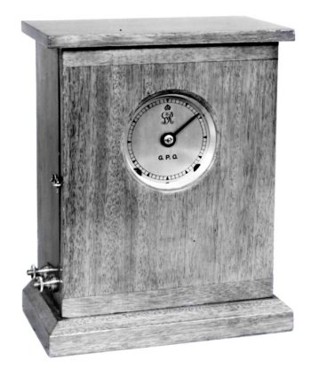
Clock No. l7A is an 8 day mechanical lever-movement, housed in a rectangular mahogany case. The movement is wound from the front, and the winding key is kept inside the case. The clock is provided with a small circular dial divided into 60 divisions and has only one hand.
|
Overall width |
8in. |
|
Diameter of dial |
3in. |
|
Depth (back to front) |
5in. |
|
Height |
10in. |
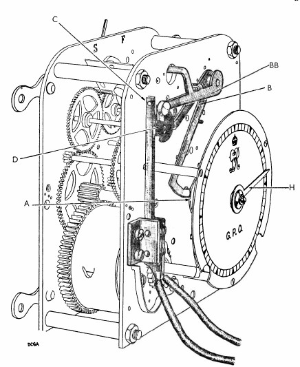
3. Description of movement
The movement consists of two spring-driven time trains. The first is a lever and escapement-controlled train, driving the single hand H. The second, which has no escapement, drives cam D which operates contacts C.
Cam A, attached to the axle of hand H, operates the lever arms B and BB at half-hourly intervals, when the hand is in the position equivalent to 6 and 12 o'clock. The operation of the levers B and BB releases the time trains associated with the cam D, which in turn operates contacts C. The contacts C close, and complete the bell circuit for approximately 3 seconds.
Drawing - 7580.
|

