P.O. ENGINEERING DEPT.
ENGINEERING INSTRUCTIONS
MISCELLANEOUS
TIME
B 3342
Issue 2, 4.9.58
ELECTRICAL CLOCKS - PULSE TYPE
Clock No. 62A - Installation
1. General
 This Instruction gives information on the installation of Clocks No. 62A. A description of this type of clock, and a list of relevant Instructions, diagrams and drawings, are given in B 1342. This Instruction gives information on the installation of Clocks No. 62A. A description of this type of clock, and a list of relevant Instructions, diagrams and drawings, are given in B 1342.
2. Installation
Specification T 9083 gives details of the installation and cabling of a Clock No. 62A when used for traffic
call-counts in manual exchanges. 30 second and one second pulses are required to drive the clock and these are derived from the master clock
(Clock No. 36). A Bell
No. 48A is normally provided, which should be modified for single stroke working, but may be used as a trembler bell. It will then ring for 30 seconds every half hour until the Clock No.62A is switched off. The operating current for the bell is 300mA.
Additional bells may be provided in large switchrooms.
3. If continuous operation is required, i.e. the start-stop facility is not required, the necessary circuit changes are shown on Diagram GMT 67/1.
The second pin on the hour disc was used to produce one
of the 30 minute pulses. This pin was only fitted to models earlier
than the Mark 5.
Induced circa 1951.
Diagrams - GMT67/0,
GMT67/1 and
GMT67/2.
Drawings - CD 1239 and P/T 52.
P.O. ENGINEERING DEPT.
ENGINEERING INSTRUCTIONS
MISCELLANEOUS
TIME
B 1342
ELECTRICAL CLOCKS - PULSE TYPE
Clock No. 62A - Description
1. General
 Clocks No. 62A were first used with associated apparatus to give 1 hourly audible warnings during traffic call-counts in telephone exchanges.
They superseded Clocks No. 17A for new exchanges where
master clocks (Clocks No. 36) were provided. They may now be used to provide a
30 minute signal to operate other electrical equipment. Clocks No. 62A were first used with associated apparatus to give 1 hourly audible warnings during traffic call-counts in telephone exchanges.
They superseded Clocks No. 17A for new exchanges where
master clocks (Clocks No. 36) were provided. They may now be used to provide a
30 minute signal to operate other electrical equipment.
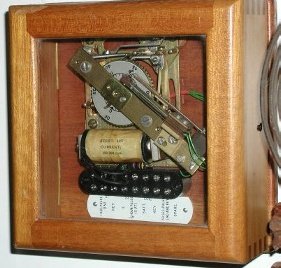
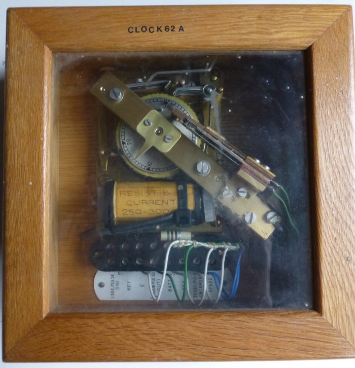
2. The original Clocks No. 62A (see picture above) had polished mahogany cases of size 11in. x 10in.
x 3in. The latest model has an oak case of size 7in. x 7in. x 3in. The cases are drilled for wall
mounting.
The above picture shows a typical arrangement of a Clock No. 62A but in the latest model the terminals are assembled in a single strip with a single label along the bottom of the clock and the movement is mounted directly on the back of the clock case. The terminal arrangement of the latest model permits
'start and reset' or 'continuous' operation.
3. Operation
Start-Stop
-
When the START key is operated 30 second pulses drive the ratchet mechanism and rotate wheel W one revolution per hour.
-
Spring-set S2 is operated at half hourly intervals by pin P2 set in wheel W.
-
Spring-set S1 'makes' at 29.5 minutes and 'breaks' at 584- minutes; it also 'makes' at
59.5 minutes and 'breaks' at 28.5 minutes. Between 29.5 and 58.5 and between
59.5 and 28.5 S1 remains 'made' and prepares the automatic 1 second pulse resetting circuit. Spring-set
S1 is controlled by pin P1 set in wheel W.
-
Spring-set S2 operates at 30 minutes and 60 minutes for a period of 30 seconds and connects earth to the bell or other device. This pulse is repeated every half-hour until the start key is restored to normal, when the clock resets automatically via
S1 springs to 28.5 or 58.5, as explained in (c).
4. Operation
Continuous
A start key is not provided and the
1 second resetting pulse is not required. If necessary the clock can be reset by manual operation of the drive magnet. The 30 second pulse from the master clock is connected to the COIL-KEY terminal (Diagram GMT 67/0), or terminals 6 and 7 are strapped (Diagram GMT 67/1).
5. Electrical details
The joint resistance of the clock coil and shunt is between 75ohms and 10ohms, and the operating current is between 250mA and 300mA.
Introduced circa 1957.
 |
 |
| Old style case |
New style case |
Additional Pictures
Mark 5

Mark 5

Mark 6

Mark 6


|