|
This section is based on a Teleprinter No. 7 document but
has additional information added for all types of Telegraph instrument
covers.
Teleprinters No. 7 are issued without covers and covers
of the appropriate type must be requisitioned as separate items.
Types of cover
In 1947 the following covers are available for general use:-
-
"Cover, Teleprinter, No. 1" and "Cover No. 25" - Dust
covers.
-
"Cover, Teleprinters, Nos. 4, 5 and 7" and "Cover No.
40" - Sound-reducing covers.
In addition, a number of obsolescent sound-reducing
covers, "Covers, Teleprinter, Nos. 2 and 3", are in use. All covers are
suitable for both "7B" and "7D" machines.
Purpose of sound-reducing covers
Sound-reducing covers are designed to give a substantial reduction in the
noise level of a working teleprinter; they are not intended to completely
silence a machine. These covers, although provided with a base, are not
suitable for carrying teleprinters in and must not be used for this purpose.
The carrying handles, where fitted, are in the correct position for lifting
the cover and base only.
Non-interchangeability
The covers and bases of "Covers Nos. 2, 3, 5 and 7" should not be
dissociated as they are not fully interchangeable. The main parts and the
hoods of "Cover No. 4" should be treated similarly.
"Cover, Teleprinter, No. 1"
This is the standard dust cover for "Teleprinters No. 7, Page and Tape." It
is a felt-lined sheet-steel cover, which fits over the main portion of the
mechanism, but leaves the printing and keyboard units exposed.

COVER, TELEPRINTER No. 1
"Cover, Teleprinter, No. 2"
This is an early type of sound-reducing cover for page-printing machines,
now superseded. It is similar in general construction to the No. 3 cover,
except that the hinged lid is fitted at an angle of 45 degrees to the horizontal and
the distance between the paper knife and the cutting edge of the glass is
approximately three inches.
Where this leads to a complaint of paper wastage, a
"Cover, Teleprinter, No. 5 or No. 7" should be fitted.
"Cover, Teleprinter, No. 3"
This is a sound reducing cover for "Teleprinters No. 7, Page," and is now
superseded by the No. 5 and No. 7 types. It is suitable only for use on
machines on which stationery in roll form is used. The "Cover, Teleprinter,
No. 3", which is similar in general appearance to the "Cover, Teleprinter,
No. 5" (shown in Fig. 2), consists of a sound-absorbing base and a
felt-lined metal cover which completely encloses the teleprinter except for
the keyboard unit. The cover is fitted so that it may either be hinged back
or lifted clear of the base. A hinged lid, which is set at an angle of
approximately 30 degrees to the horizontal, enables the roll of printing
paper to be inserted without raising the cover. A plate-glass panel is
fitted in the lid to enable the operator to view the printing; the paper
emerges behind this panel, the rear edge of which is bevelled to facilitate
tearing off the paper. An adjustable paper guide behind the panel enables
the paper gap to be adjusted to suit either single or duplicating paper. The
distance between the bevelled edge of the glass and the teleprinter paper
knife is approximately 11in.
The base has foul locating recesses for the
teleprinter feet and, to enable the teleprinter to bed down properly, it may
be necessary to reduce the diameter of the rubber feet. If the machine is
not properly seated, contact between the machine and the cover may cause
excessive noise. A clip is provided at the right-hand rear corner of the
base for securing the instrument cords so that they do not interfere with
the free movement of the carriage.
An external handle for rotating the platen is provided
and, before the cover is raised or lowered, the handle must be withdrawn and
set so that the coupling on the end of its spindle is clear of the platen
knob on the machine. A slotted plate and a pin on the spindle are provided
for this purpose. A push-button is provided for operating the starter-switch
control mechanism, as on the standard dust cover.
The mechanism for operating the end-of-line bell is
mounted inside the cover. The bell-trip arm (requisitioned separately as
"Part No. 1 /SAR/1") is secured to the left-hand end of the carriage, by
means of the paper-chariot fixing screw and nut and also an additional screw
supplied with the bell-trip arm to replace the existing screw, which secures
the end-plate to the carriage casting. The trip arm engages with the trip
crank on the bell mechanism, which is adjusted so that the bell-hammer is
operated at the normal distance from the end of the line. The method of
fitting the tabulating indicator is described in C 3909.
"Cover, Teleprinter, No. 4"
This is a sound-reducing cover for tape-printing "Teleprinters No. 7." This
cover consists of a No. 1 cover and a detachable metal hood, which
completely encloses the printing unit. The hood, which is felt-lined and
provided with a hinged glazed lid, is secured in position on the dust cover
by means of two clasps. A base is not provided for this type of cover.
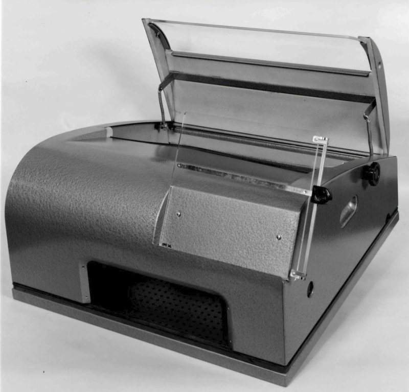
"Cover, Teleprinter, No. 5"
This is a sound-reducing cover for page-printing "Teleprinters No. 7." It is
suitable for stationery made up in roll or pack form.
COVER, TELEPRINTER No. 5
The cover is similar in appearance to the No. 3 cover
and incorporates the following improvements over the No. 3 cover but is
otherwise as described in pars. 7 to 10:-
-
An adjustable slot is provided in the back of the
cover. Stationery in pack form cannot be carried under the cover and
this slot provides the entry for the paper, which is kept behind the
teleprinter.
-
The top of the cover and the hinged lid are slightly
different from those of the No. 3 cover, the main difference being that
the angle of the glass is nearer to the horizontal to suit the paper
outlet on sprocket-feed machines.
-
An end-of-line bell mechanism and platen-knob
assembly of improved design have been introduced.
The approximate dimensions of the No. 5 cover (with its lectern) are:
25.5in. wide x 22in. deep x 14.5in. high.
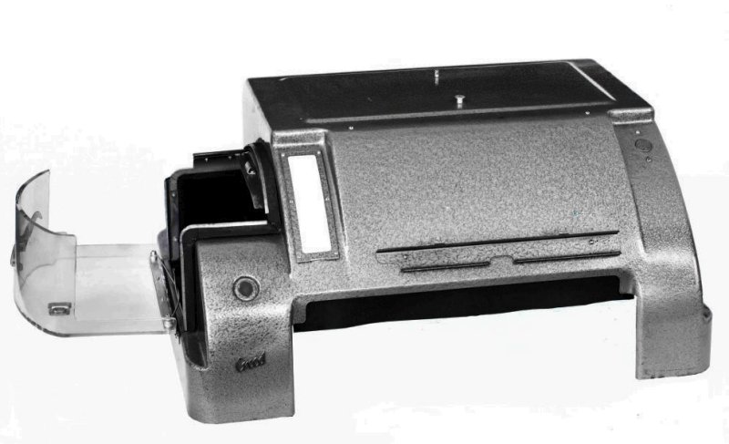
"Cover, Teleprinter, No. 7"
This cover is an improved sound-reducing cover for use with page-printing
"Teleprinters No. 7", using paper in roll or pack form. It provides the same
facilities as the No. 5 cover, except that the end-of-line bell mechanism is
not provided.

COVER, TELEPRINTER No. 7 (BURGESS)
There are two manufacturers of "Covers, Teleprinter,
No. 7":-
-
The cover made by the Burgess Products Ltd. is
illustrated in Fig. 3. The cover and the base are made of sheet
aluminium and lined mainly with glass wool. These covers are either
labelled with a Burgess name-plate or are marked "7BUR" on the underside
of the base.
-
The cover made by the Power Equipment Co. is not
illustrated, but is similar in general appearance to the Burgess
Products type. The cover and base are made from steel lined with "Multopren"-
a porous plastic material - and are marked "7 PE" on the underside of
the base. There are a few minor differences in design but the complete
cover is interchangeable with the Burgess Products type.
On both covers, rubber padding is provided on the
main base as a seating for the cover, and around the keyboard aperture to
reduce transmission of sound by direct contact. The cover cannot be hinged
back but must be lifted clear of the base when access to the teleprinter is
required. A hinged Perspex window (fitted with metal paper knife) is
provided to enable the operator to see the printing. The distance between
the paper knife on the cover and the teleprinter paper knife is
approximately 7/8in. The rear portion of the cover is hinged to enable rolls
of paper to be inserted without removing the complete cover. The base has
four resiliently-mounted metal cups to locate the teleprinter feet. They are
not adjustable but are greater in diameter than the rubber feet to allow for
variation of dimensions between machines. Spring clips are provided on the
base to hold the instrument cords clear of the carriage mechanism. The
external knob for rotating the platen cannot be locked in the disengaged
position so it is important that it should be held out by the hand whenever
the cover is being removed or replaced. This is necessary because,
otherwise, there is a danger of the coupling dog fouling the teleprinter
platen knob and damaging its spindle. A push-button, for operating the
motor-starting switch, is provided as on the standard dust cover.
The lectern ("Cover, Teleprinter, Part No. 10") is
mounted on the right-hand side of the cover, as shown in Fig. 3, and is
secured in position by three screws and washers. It should be removed when
preparing the cover for transit. The message tray ("Cover, Teleprinter, Part
No. 11") is not illustrated but is designed to rest on the rear flap when in
use. It is not secured in any way to the cover and may he lifted clear, e.g.
by an operator, when it is desired to open the rear flap. The tray has two
equal message compartments each 12in. x 8in. and lin. deep.
The dimensions of the cover without lectern or
message tray are approximately 24in. wide x 23in. deep x 11.5in. high. With
lectern and message tray in place these dimensions become 25.5in. wide x
24.5in. deep x 16in. high.
"Cover No. 8"
See E.I. Telegraphs,
Teleprinter D1007.
"Cover No. 9"
See E.I. Telegraphs,
Teleprinter D1007.
COVER, TELEPRINTER No. 9
"Cover No. 10"
See E.I. Telegraphs,
Teleprinter C1055.
COVER, TELEPRINTER No. 10
"Cover No. 11"
Sheet-iron. For covering keyboard of Teleprinters No. 7 ... and Typewriters
Telegraph No .... during practice of touch typing.
"Cover No. 14"
Non-noise-reducing steel cover, felt lined. For Printing-Reperforators No.2.
"Cover No. 19A"
Non-noise-reducing steel cover, felt lined. For Printing-Reperforators No.
1.
Alternative to "Cover No. 19B".
"Cover No. 19B"
Non-noise-reducing steel cover, felt lined. For Printing-Reperforators No.
1.
"Cover No. 21"
Metal cover 19" x 5" x 1.5" deep, 2 slots each end
For protecting rear of Panel Telegraph No. 71B when rack mounted.
"Cover No. 23"
Printing-Reperforator No. 1
Fabric dust cover for Typewriter, Telegraph No.8 ...
"Cover No. 24"
Cloth dust cover for Typewriter, Telegraph No. 9.
"Cover No. 25"
This is a dust cover for use with the "Teleprinter No. 7B/PKN3" and is
similar in construction to the "Cover, Teleprinter, No. 1" except that the
front left-hand corner is cut away to give access to the perforator unit.
This cover is not suitable for use with "Teleprinters No. 7B/RP".
"Cover No. 34"
Noise-reducing, lined with glass wool, with base. For Printing-Reperfrs.
Nos. 1 and 2.
When used with Printing-Reperforator No. 1
To be requisitioned seperatly if reqd. :-
1 Cover, Teleprinter, Part No. 10
When used with Printing-Reperforator No. 2
To be requisitioned separately:-
1 Part No. 1/SPL/691.
"Cover No. 35"
Fabric dust cover for teleprinters and other telegraph apparatus.
Dimensions - overall 22 x 22" x 10" high
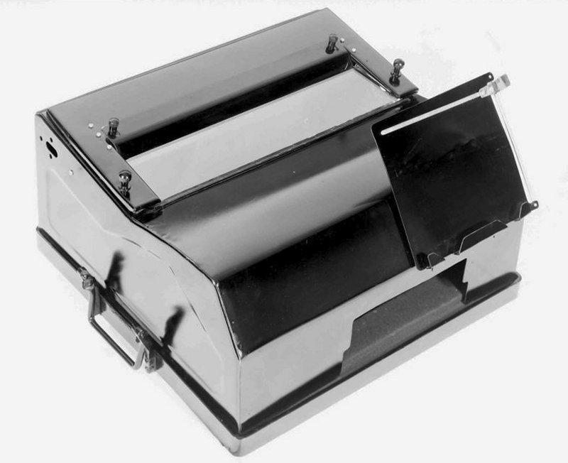
"Cover No. 40"
This is the standard sound-reducing cover for use with "Teleprinters No.
7B/PKN3 and No. 7B/RP" and is similar in construction to the "Cover,
Teleprinter, No. 7" manufactured by Messrs. Burgess except that the front
left-hand corner is cut away to provide ready access to the perforating
mechanism. Otherwise the cover completely encloses the teleprinter except
for the tape-roll holder. The overall dimensions are: 27in. wide x 29in.
deep x 18in. high, including the message desk ("Cover, Teleprinter, Part No.
10"). The message tray ("Cover, Teleprinter, Part No. 11") is not suitable
for use with "Covers No. 40".

COVER, TELEPRINTER No. 40 - Fitted to a Teleprinter No.
7B
|