DATEL MODEM No's 2A and 2B | ||||||||
|
This modem is capable of half or full duplex data communication at any
speed up to 300 baud, via a single pair (600ohm) type telephone line.
The modem complies with the European CCITT standards.
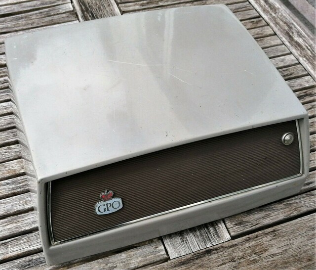
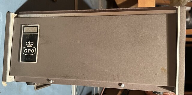
Datel Modem No. 2A is a standalone/table model, whilst the Datel Modem No. 2B is rack-mounted. Date connection is via a 25 way "D" type socket that conforms to the RS232 specification. Used on the Datel 200 service. Additional Information
Line and data
connections
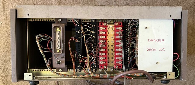
Data connections to and from the computer or terminal equipment are made via a standard 25 way 'D' type socket with RS232 specification voltage levels. Connections to the communications line and auto answer strapping are made via the 16 way terminal block situated under the rear cover plate. The communications line is connected to terminals 11 and 12.For auto answer use, link terminals 13 and 15, connect a 1mf 250v non-polarised capacitor between terminals 6 and 7, and a Thermistor No. 1A between terminals 5 and 8. After installation of the auto answer modification the RING INDICATOR output (pin 22 on 25 way 'D' socket) will go HIGH in unison with the ringing voltage detected from the communications line, giving an indication to the computer that an incoming call is present, and if so desired, may be answered by taking pin 20 HIGH. Modem use All functions of the Datel Modem No. 2 can be controlled via, either pin 20 on the 25 way 'D' connector, or the two brown test jacks situated under the hinged front panel. It is important to note that the two test jacks OVERRIDE functions from the interface connections. For normal use ensure that the brown jack plugs on the front panel are in the "AUTO" and "DATA" positions. Dial the remote computer number, establish your connection on hearing the high pitched answer tone, and within 15 seconds either take pin 20 on the 25 way 'D' type interface socket HIGH, OR move the test jack plug on the control module to the "CALL" position. Either of these operations will loop and hold the line, and turn on the modem carrier tone, enabling you to replace your handset, and eliminate any extraneous room noise. Always remember to return the jack to the 'AUTO' position or remove the signal on pin 20 after you have finished with a data call, otherwise your line will be held as long as either of these signals are present. Other signals are available on the 25 way 'D' connector such as CARRIER DETECT. This signal is HIGH as long as a carrier tone from a remote computer is present. Loss of this signal tells the attached computer to abort the call, stop a program and reset the modem, thus returning the line to normal. Documents
Diagrams Other Documents
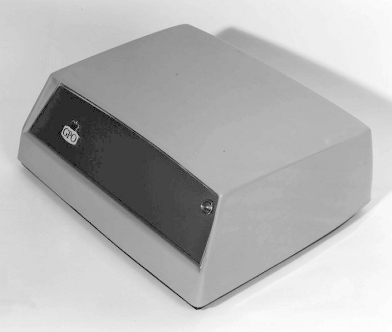
Datel Modem No. 2A
Datel Modem No. 2B - Front view
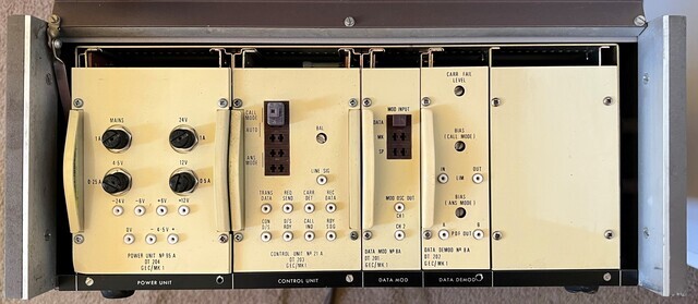
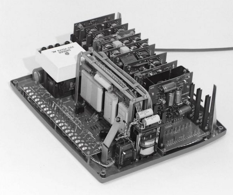
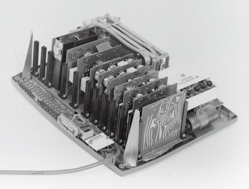
Datel Modem No. 2B - Front cover removed
Datel Modem No. 2B - Rear View
Datel Modem No. 2A
Datel Modem No. 2A
Datel Modem No. 2A
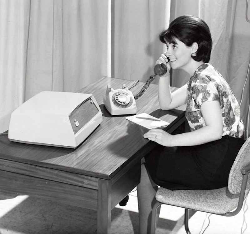
Datel Modem No. 2A (Marketing picture)
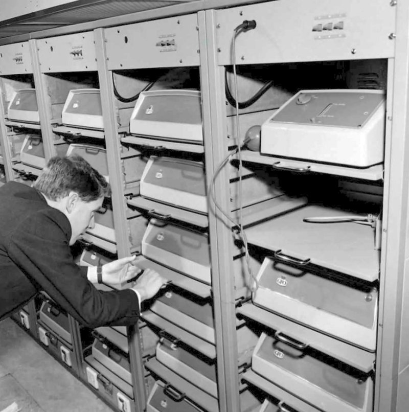
Datel Modems No. 2A in a customers premises
|
||||||||
Last revised:FM2 | ||||||||